In the engineering department at eptahub.com, precision is everything. When a junior designer or a new procurement officer walks into my office and asks, “What is the meaning of FDM?”, my first response is always: “Which industry are you talking about?”
Then, as a mechanical engineer, I will pivot deeply into the most revolutionary physical application of the acronym: Pemodelan Pemendapan Bercantum (3D Printing). We will tear down the physics of thermoplastic extrusion, examine the mathematical weaknesses of layered manufacturing, and explain how we use FDM to bypass massive tooling costs on the factory floor.
Where Does FDM Stand For What?
If you are outside the mechanical manufacturing sector, here is exactly how your specific industry defines the term.
1. Information Technology & Telecom
- What does FDM stand for in computer networks? Frequency Division Multiplexing.
- Realiti Kejuruteraan: This is a foundational telecommunications technology. It is the process of taking a single physical transmission medium (like a copper wire or a fiber optic cable) and splitting its total bandwidth into multiple, distinct, non-overlapping frequency bands. Each band carries a separate signal. This is exactly how your television receives hundreds of different channels through a single coaxial cable without the signals colliding.
2. Corporate Enterprise & Software
- What is the meaning of FDM in business? Financial Data Management (or Field Data Management).
- Realiti Kejuruteraan: If someone asks what does fdm stand for in workday (a massive HR and financial software platform) or what does fdm stand for in finance, they are referring to the architecture used to consolidate, map, and audit financial data across disparate global systems before it hits a general ledger. Similarly, what does fdm stand for in marketing atau what does fdm stand for in retail often refers to Field Data Management—the logistical tracking of on-the-ground sales metrics or inventory distribution.
3. Entertainment & Gaming
- What does fdm stand for fortnite or what does fdm stand for in gaming? First Drop Meta (or occasionally, Free Death Match).
- Realiti Kejuruteraan: I am a mechanical engineer, not a professional gamer. However, in gaming analytics, FDM often refers to the strategic metagame of where players choose to land or deploy at the very beginning of a battle royale match to optimize their resource gathering.
Now that we have successfully isolated the software and telecom definitions, we will dedicate the remainder of this technical guide to the physical, manufacturing definition.
The Mechanical Core: What Does FDM Stand For in 3D Printing?
When a mechanical engineer asks what does fdm stand for in 3d printing, the answer is Pemodelan Pemendapan Bercantum.
Invented by S. Scott Crump in the late 1980s (who subsequently founded Stratasys), FDM is the most widely utilized additive manufacturing technology on earth.
- Legal Note: Stratasys heavily trademarked the acronym “FDM”. Therefore, to avoid lawsuits, the open-source community (like the RepRap project) coined the term FFF (Fused Filament Fabrication). From an engineering and physics standpoint, FDM and FFF are the exact same mechanical process.
The Physics of FDM Additive Manufacturing
FDM does not use lasers, vats of toxic resin, or metallic powders. It relies on the phase-change thermodynamics of standard engineering plastics.
Here is the exact mechanical sequence of how an FDM machine operates:
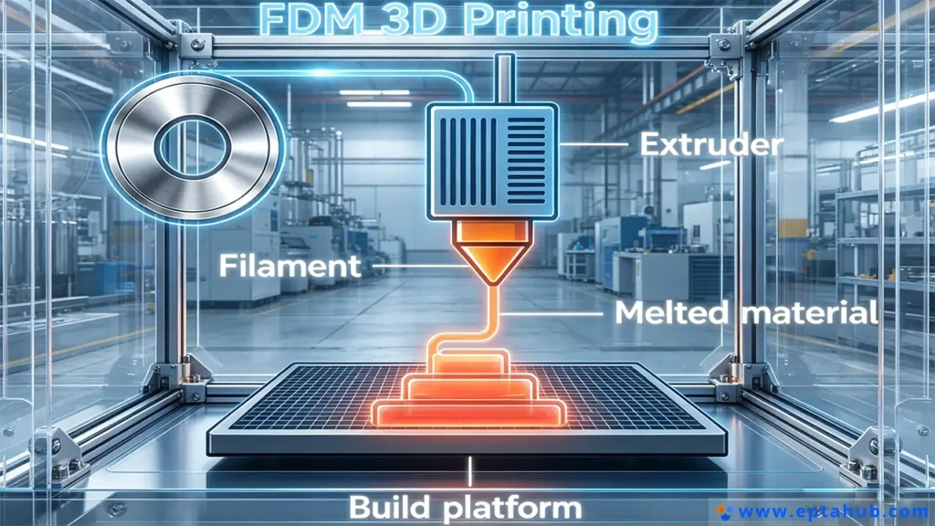
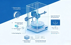
- The Raw Material: A continuous spool of solid thermoplastic filament (typically 1.75mm or 2.85mm in diameter) is fed into the machine. Common materials include PLA, ABS, PETG, and aerospace-grade ULTEM.
- The Extruder & Hotend: A stepper motor (the extruder) physically grips the filament and pushes it down into a mathematically engineered thermal chamber (the hotend). The hotend is electrically heated to a temperature precisely above the material’s Glass Transition Temperature (Tg) and into its melting phase (typically between 200°C and 300°C).
- The Nozzle: The viscous, molten plastic is forced through a microscopic brass or hardened steel nozzle (commonly 0.4mm in diameter).
- Kinematic Deposition: The CNC gantry of the printer moves the nozzle in the X and Y axes, “drawing” a 2D cross-section of the CAD model onto a build plate.
- Z-Axis Stacking: Once one layer is drawn, the build plate lowers (or the print head raises) in the Z-axis by a fraction of a millimeter (e.g., 0.2mm). The machine draws the next layer directly on top of the previous one. The heat of the new layer melts into the layer below it, thermally fusing them together.
Engineering Matrix: FDM vs. Alternative 3D Printing Technologies
To truly understand what is the meaning of FDM in a factory environment, you must understand its limitations compared to other additive processes. We do not use FDM for everything. At eptahub.com, we select the technology based on strict mechanical requirements.
| Engineering Parameter | FDM (Pemodelan Pemendapan Berlakur) | SLA (Stereolithography) | SLS (Sintering Laser Selektif) |
|---|---|---|---|
| Keadaan Bahan Utama | Solid Thermoplastic Spools | Resin Fotopolimer Cecair | Microscopic Polymer Powder |
| Phase Change Trigger | Thermal Melting (Heat) | Photochemical Curing (UV Laser) | Thermal Fusion (Infrared Laser) |
| Toleransi Dimensi | Moderate (± 0.2mm) | Extremely High (± 0.05mm) | High (± 0.1mm) |
| Mechanical Isotropism | Anisotropic (Weak in Z-axis) | Isotropic (Uniform strength) | Isotropic (Uniform strength) |
| Internal Geometry | Requires breakaway support structures | Requires breakaway support structures | Self-supporting (No supports needed) |
| Primary Industrial Use | Jigs, Fixtures, Structural prototypes | High-detail aesthetic models, molds | Complex, functional end-use parts |
The Greatest Weakness of FDM: Z-Axis Anisotropy
The most critical engineering concept you must understand about FDM is Anisotropy.
If you take a solid block of injection-molded ABS plastic, it is Isotropic. This means its mechanical strength is identical regardless of which direction you pull on it.
An FDM part is Anisotropic. Because the part is built by stacking microscopic, semi-molten cylinders of plastic on top of each other, the bond between the layers (the Z-axis) is vastly inferior to the continuous plastic strand within the layer (the X and Y axes).
If you test the tensile strength of an FDM part, it might withstand 40 Megapascals (MPa) of force when pulled along the X/Y axis. But if you pull it apart vertically (along the Z-axis), it might snap at only 15 MPa because the layers simply delaminate (peel apart).
Engineering Case Study: The Broken Assembly Jig
To illustrate how critical it is to understand FDM kinematics, let us review a failure that occurred in our assembly division at eptahub.com.
Senario: We were manufacturing a high-volume batch of aluminum pneumatic manifolds. To speed up the manual assembly process, a junior engineer designed a custom U-shaped holding jig. To save the $2,000 cost and 3-week lead time of Pemesinan CNC the jig out of aluminum, they correctly opted to 3D print it using our industrial FDM system with Carbon-Fiber reinforced Nylon (PA-CF).

Kegagalan: The junior engineer sent the STL file to the FDM printer. The printer automatically laid the U-shaped jig flat on its back (to minimize the need for support structures) and printed it.
On the factory floor, an assembly technician placed the heavy aluminum manifold into the U-shaped jig and clamped it down tight. The right arm of the U-shaped jig immediately snapped off under the shear load.
Punca Kejuruteraan:
The junior engineer treated the FDM part as if it were an isotropic block of metal. They did not account for the Z-axis weakness.
Because the part was printed lying flat on its back, the plastic layers were stacked perfectly horizontal. When the technician applied a clamping force against the upright arm of the “U”, the shear force was directed exactly along the weakest point of the part: the layer adhesion lines (the Z-axis). The layers simply sheared apart.
Pembaikan:
We did not change the design or the material. We simply changed the Print Orientation.
I had the technician re-slice the G-code, rotating the U-shaped jig 90 degrees so that it printed standing upright on its side. Now, the continuous, incredibly strong strands of extruded carbon-fiber nylon (the X/Y axis) ran continuously up and down the arms of the “U”.
When placed back on the assembly line, the clamping force was now pushing against the continuous strands, rather than trying to peel the layers apart. The part survived thousands of assembly cycles without a single micro-fracture.
When utilizing FDM, you are not just designing the geometry of the part; you are actively engineering the internal microscopic grain structure of the polymer.
The Fluid Dynamics of FDM: Volumetric Flow Rate
The most common error junior machine operators make is attempting to decrease lead times by simply cranking up the “Print Speed” variable in their slicing software (e.g., changing it from 50 mm/s to 150 mm/s). Inevitably, the extruder stepper motor begins violently clicking, the filament strips out, and the machine jams.
They fail to understand the absolute physical bottleneck of FDM: Volumetric Flow Rate (mm3/s).
A printer’s hotend (the thermal melt zone) has a maximum capacity of thermal energy it can transfer to a solid polymer within a given second. If you feed solid plastic into the melt zone faster than the heater cartridge can melt it, the solid plastic hits the microscopic nozzle opening and acts as a cork.
To prevent catastrophic print failures, we mathematically constrain our machine speeds using this strict formula:
Volumetric Flow Rate = Layer Height (mm) × Extrusion Width (mm) × Print Speed (mm/s)
- Contoh: If we are printing an ABS part with a 0.2mm layer height, a 0.4mm extrusion width, at a speed of 100 mm/s.
0.2 × 0.4 × 100 = 8.0 mm³/s. - If the specific hotend on our machine has a maximum melt capacity of 12.0 mm³/s, the print will succeed. If the operator tries to increase the speed to 200 mm/s, the required flow rate becomes 16.0 mm³/s. The hotend will physically fail to melt the plastic in time, resulting in under-extrusion and total structural failure of the part.
Thermodynamics: Defeating Thermal Contraction and Warping
When engineers transition from printing basic PLA to industrial-grade, high-strength thermoplastics like Polycarbonate (PC), ABS, or ULTEM, they collide with a brutal thermodynamic reality: the Coefficient of Thermal Expansion (CTE).
Plastics expand when heated and contract when cooled. In FDM, we are laying down a line of plastic at 260°C onto a previous layer that has already cooled down to 90°C.
- As the new, top layer cools, it mathematically shrinks.
- Because it is thermally fused to the cooler, already-shrunk layer below it, this differential contraction creates massive internal shear stress.
- As these stresses compound layer by layer, the force literally bends the plastic, pulling the corners of the part violently off the build plate. This is known as Warping atau Curling.
In the hobbyist market, people try to solve this by smearing glue on the build plate. In industrial engineering, we solve this with thermodynamics.
True industrial FDM machines do not rely on heated build plates alone; they utilize Actively Heated Build Chambers. The entire atmospheric envelope inside the machine is heated to a temperature precisely below the material’s Glass Transition Temperature (Tg). For ABS, the chamber is held at exactly 80°C to 90°C.
By keeping the entire printed part in a state of thermal equilibrium, we prevent the plastic from contracting during the print. Only when the final layer is finished do we initiate a controlled, mathematically stepped cooling sequence (annealing) to slowly bring the part down to room temperature, permanently locking the polymer chains in place without inducing warp.
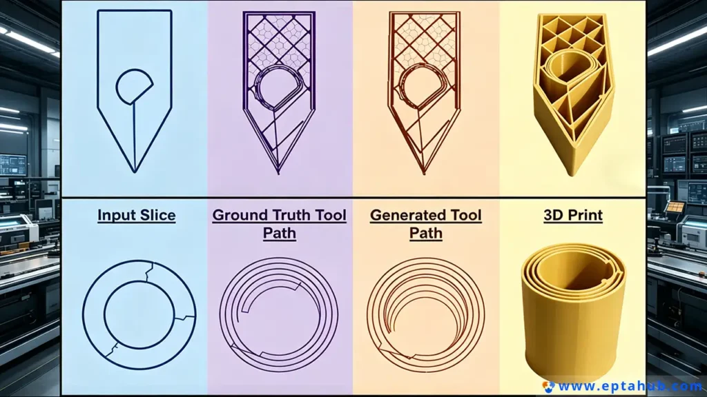
G-Code Generation: Engineering the Internal Structure
Unlike Pengilangan CNC, where you start with a solid billet of aluminum, FDM is an additive process. This allows us to do something structurally impossible in traditional machining: we can dictate the internal cellular geometry of a closed solid.
When generating the toolpath (G-code) for an FDM part, engineers must define two critical structural parameters: Perimeters (Shells) dan Infill.
The Infill Fallacy
A common misconception is that to make an FDM part stronger, you must print it completely solid (100% Infill). This is a waste of engineering time, raw material, and money.
In structural mechanics (specifically when dealing with bending moments and I-beams), the material closest to the central neutral axis does very little work. All the extreme tensile and compressive stresses occur on the outer surfaces of the part.
The Perimeter Mandate
Instead of increasing the internal infill to 100%, we increase the number of Outer Perimeters (the solid walls that form the exterior shell of the part).
- A part with 2 perimeters and 100% solid infill will take 14 hours to print and will snap under a 50kg load.
- A part with 6 solid perimeters and only a 20% Gyroid (3D cellular) internal infill will take 6 hours to print, use half the material, and withstand a 75kg load.
At eptahub.com, we engineer our FDM profiles to maximize perimeter wall thickness to absorb localized impacts and kinetic shear forces, utilizing sparse internal infill purely to support the top-facing horizontal roofs during the printing process.
The Engineer’s Verdict
When you ask what does FDM stand for, you are asking about the most disruptive tool in modern mechanical engineering.
Fused Deposition Modeling is not a magic box that perfectly replicates CAD files. It is a highly volatile, anisotropic manufacturing process governed by fluid dynamics, thermal contraction, and layer adhesion physics.
When utilized incorrectly by untrained operators, it produces weak, warped, useless plastic toys. But when its thermodynamic principles are strictly controlled, FDM allows an engineering firm to bypass tens of thousands of dollars in tooling costs, producing complex, lightweight, carbon-fiber reinforced jigs, fixtures, and end-use parts in a matter of hours instead of weeks.
Respect the layer lines, orient your parts against the shear loads, and mathematically control your volumetric flow.
Rujukan
To ensure your additive manufacturing processes align with global industrial standards and terminology, refer to the following definitive resources:
1.ASME Y14.46-2022 (Product Definition for Additive Manufacturing)
A critical standard for mechanical engineers. It provides the strict GD&T (Geometric Dimensioning and Tolerancing) rules for how to properly define layer orientations, infill structures, and anisotropic material properties on a 2D engineering drawing sent to an FDM facility.
Pautan: ASME.org