In my 12 years of evaluating supplier capabilities and auditing manufacturing pipelines at eptahub.com, I have had countless arguments with junior design engineers who believe their job ends when the CAD model is finished. They hand over a beautifully rendered 3D STEP file and assume the factory simply presses “print.”
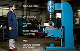
This is a fundamental misunderstanding of industrial manufacturing. A 5-axis Fraisage CNC machine—a half-million-dollar piece of cast iron and servos—does not understand 3D models. It is completely blind to your CAD geometry. It only understands a highly rigid, alphanumeric programming language.
When a machinist or mechanical engineer asks, “What does the G-code mean?”, they are asking about the fundamental bridge between digital theory and physical reality. If your CAD is the architectural blueprint, the G-code is the step-by-step instruction manual handed to the bricklayer. If the instructions are wrong, the machine will blindly drive a carbide endmill into a steel vise at 15,000 RPM, shattering a $12,000 spindle in a fraction of a second.
What Does the G-Code Stand For?
Let us answer the foundational vocabulary question immediately: What does code G stand for?
Officially, defined by the historic EIA-274D (RS-274) standard, the “G” stands for Geometry ou General Preparatory Commands.
When you issue a command starting with the letter G, you are telling the CNC controller’s microprocessor to prepare the machine’s axis servos for a specific type of geometric movement or to establish a specific coordinate system. You are dictating comment the cutting tool will move through three-dimensional Cartesian space (X, Y, Z axes, and rotational A, B, C axes).
What is G-Code in CNC Machine Operations?
To understand what is g-code in cnc machine terminology, you must look at it as a stream of raw kinetic data. The machine reads the code block by block (line by line) from top to bottom.
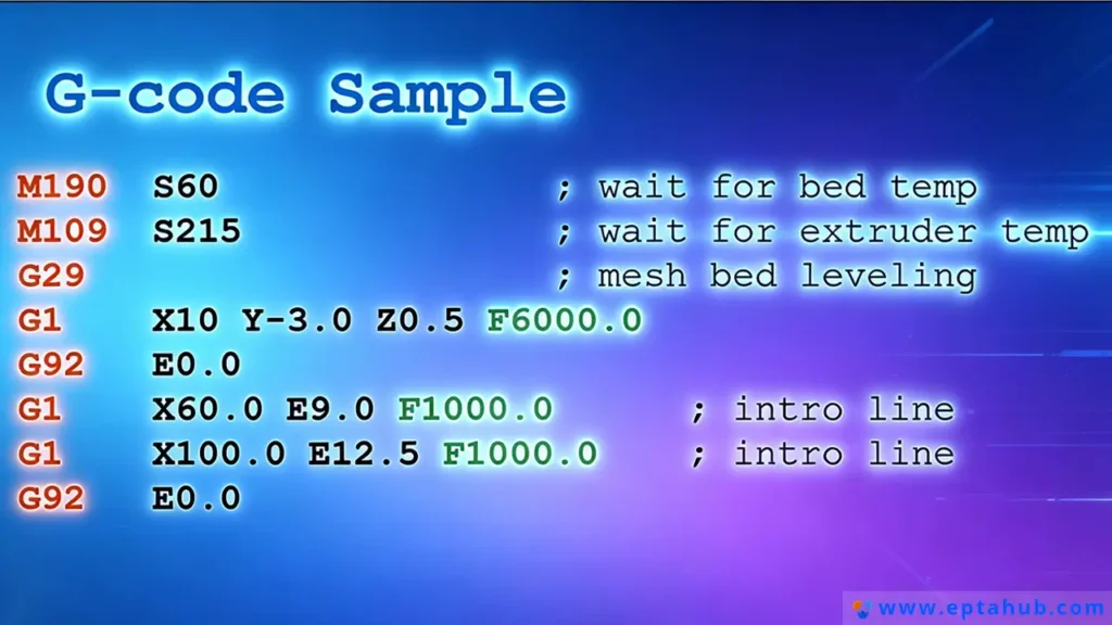
Here is a foundational g-code example of a single block:
N010 G01 X50.0 Y25.0 F250.0
As an engineer, here is how you decode that syntax:
- N010: The block number (Line 10).
- G01: The Preparatory Code (Linear Interpolation—move in a straight line while cutting).
- X50.0 Y25.0: The target Cartesian coordinates (move to X=50mm, Y=25mm).
- F250.0: The Feed Rate (move at exactly 250 millimeters per minute).
The CNC controller takes this line, calculates the exact voltage required for the X and Y servomotors to reach the destination simultaneously, and executes the cut.
What Does M Code Stand For?
You cannot operate a machine using geometry alone. The machine has physical hardware that must be toggled on and off: coolant pumps, spindle motors, hydraulic chucks, and chip conveyors.
This brings us to the second half of the ecosystem. When people search for what do G and M codes stand for?, they are trying to separate the geometry from the hardware.
Donc, what does m code stand for? The “M” stands for Miscellaneous ou Machine codes.
While G-codes control the path of the tool, what is m code? It is the digital switch relay. M-codes do not move the axes. They send electrical signals to the machine’s PLC (Programmable Logic Controller) to activate physical hardware states.
If you want the spindle to spin clockwise at 5,000 RPM, the geometry (G-code) cannot help you. You must use an M-code (M03 S5000). If you want to flood the cutting zone with synthetic coolant to prevent the titanium from catching fire, you issue an M-code (M08).
The Engineering Matrix: G-Code and M-Code Hierarchy
When junior programmers begin their training, they inevitably search the internet for a massive g code list pdf and try to memorize it. This is a fool’s errand.
Different machine manufacturers (Haas, Fanuc, Siemens, Heidenhain) have slight variations in their code dictionaries. However, the foundational codes are universal. Below is the strict engineering matrix we use at eptahub.com to define the absolute critical commands in a g-code list and M-code list.
Table 1: The Essential G & M Code Engineering Reference
| Command | Catégorie | Code Name | Engineering Function & Physical Reality |
|---|---|---|---|
| G00 | Geometry | Rapid Positioning | Danger. Moves all axes to the target coordinate at the machine’s maximum physical velocity. Never use this while the tool is touching the metal. |
| G01 | Geometry | Linear Interpolation | The workhorse. Moves the tool in a straight line at a strictly controlled feed rate (F-value). Used for cutting metal. |
| G02 / G03 | Geometry | Circular Interpolation | Moves the tool in a perfect arc or circle (G02 is Clockwise, G03 is Counter-Clockwise). Calculates complex simultaneous axis motion. |
| G90 | System | Absolute Positioning | Tells the machine: “Read all X, Y, Z coordinates relative to the absolute zero origin point of the workpiece.” |
| G91 | System | Incremental Positioning | Tells the machine: “Read all X, Y, Z coordinates relative to where the tool currently is right now.” |
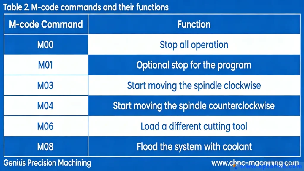
| M00 | Machine | Program Stop | Pauses the machine indefinitely. Used by operators to open the doors, clear metal chips, or flip a part manually. |
| M03 / M04 | Machine | Spindle Start | Activates the massive electric spindle motor. M03 is Forward (Clockwise), M04 is Reverse. Requires an ‘S’ value (RPM). |
| M06 | Machine | Tool Change | Triggers the robotic Automatic Tool Changer (ATC) carousel to swap out the current endmill for a new one. |
| M08 / M09 | Machine | Coolant State | M08 opens the valves to blast high-pressure liquid coolant at the tool. M09 shuts the valves off. |
| M30 | Machine | End of Program | Stops the spindle, turns off coolant, rewinds the machine memory back to Line 1, and releases the hydraulic clamps. |
The Concept of “Modality” in G-Code Programming
If you want to understand g-code programming at a senior engineering level, you must understand the concept of Modal vs. Non-Modal commands. This is where 90% of programming errors occur.
- Modal Commands: Once a modal G-code is executed, it stays permanently active until you explicitly cancel it or overwrite it with a contradicting code.
- Exemple: Si vous tapez
G01 X10.0 Y10.0 F100on line 1, the machine goes into “controlled cutting mode.” If line 2 is simplyX20.0, the machine remembers the G01 and the F100, and will continue cutting to the new X coordinate at the same speed.
- Exemple: Si vous tapez
- Non-Modal Commands: These only execute for the exact line they are written on, and are immediately forgotten by the machine on the next line. (e.g., G04 Dwell time).
Engineering Case Study: The G90 vs G91 Catastrophe
To illustrate why understanding the strict definitions of what is g code and m code is non-negotiable, consider a catastrophic failure analysis I was called to investigate at a tier-2 aerospace supplier.
Le scénario : The supplier was machining a complex turbine housing out of Inconel 718 (an incredibly hard, heat-resistant superalloy) using a 5-axis DMG Mori CNC mill. The CAM programmer made a manual edit to the text file at the very end of the program to lift the tool up and drill one final hole.
The Code Written:
N500 G91 G00 Z50.0 (Move the tool up 50mm incrementally from its current position to get clear of the part).
N510 X10.0 Y10.0 (Move to the final hole position).
N520 G01 Z-5.0 F50.0 (Plunge down 5mm to drill the hole).
L'échec : The machine executed line N500 perfectly, lifting the tool clear. It executed N510, moving over the hole. But on line N520, the spindle violently drove the 20mm solid carbide drill straight down through the Inconel part, through the hardened steel workholding fixture, and directly into the cast-iron table of the machine. The tool exploded, the spindle bearings were crushed, and the machine was knocked out of alignment. Total damage: $35,000 and 4 weeks of downtime.
La cause profonde en matière d'ingénierie :
The programmer fundamentally misunderstood Modal commands.
On line N500, the programmer issued G91 (Incremental Positioning). This is a Modal command. It altered the entire machine’s brain.
When the machine reached line N510 (X10.0 Y10.0), it didn’t move to the absolute coordinates of X10/Y10. Because G91 was active, it moved 10mm further away from wherever it currently was.
Worse, when it reached line N520 (Z-5.0), the programmer thought they were telling the machine to drill a hole 5mm deep into the part. But the machine was still in G91 (Incremental) mode. The machine thought: “Move 5mm further down from my current Z position.” The tool was hovering 50mm in the air. Moving down 5mm put it 45mm above the part. It cut nothing.
Wait, why did it crash then?
The programmer had previously set the machine to Absolute mode earlier in the program, and assumed the machine would magically revert back to it. They failed to issue a G90 (Absolute Positioning) command before line N520. If they had written N520 G90 G01 Z-5.0 F50.0, the machine would have known to dive down to the absolute Z-coordinate of -5.0mm. Instead, the machine was hopelessly lost in space, executing incremental moves until it collided with physical mass.
This is why, at eptahub.com, we do not tolerate manual edits to G-code on the factory floor without a rigid simulation verification. G-code has no common sense; it only executes the exact mathematical logic you provide.
How Modern CAM Software Generates G-Code?
In the 1980s, CNC operators would stand at the machine controller and manually punch in every single line of a g-code program. Today, at eptahub.com, a complex 5-axis aerospace impeller might require a text file containing 4.5 million lines of code. It is mathematically impossible for a human to write or verify this manually.
This is where CAM (Computer-Aided Manufacturing) software becomes the vital bridge.
When a junior engineer asks what is g-code in cnc machine terminology today, they are really asking about the output of a CAM system (like Siemens NX, Mastercam, or Fusion 360). The CAM software takes the 3D CAD model, allows the programmer to define the cutting tools, speeds, and toolpaths visually, and then mathematically translates those visual paths into raw alphanumeric g-code examples.
However, there is a critical, often misunderstood bottleneck in this process: The Post-Processor.
The Post-Processor: The Ultimate CNC Interpreter
A common misconception is that standard G-code is universally identical across all machines. This is false. While the fundamental concepts of what do G and M codes stand for remain true, a Fanuc controller speaks a slightly different “dialect” of G-code than a Haas or Heidenhain controller.
- Le problème : If you send a Haas-formatted G-code file to a Fanuc machine, the machine might misinterpret an M-code, fail to activate the coolant, and ignite the titanium workpiece.
- La solution : The Post-Processor. This is a specific script inside the CAM software that translates the generic toolpath data into the exact, rigidly formatted text file required by that specific machine’s brand, model, and age. If your Post-Processor is flawed, your $500,000 CNC machine will crash, regardless of how perfect the CAD model is.
Advanced G-Code Programming: Work Coordinate Systems (G54-G59)
If you hand a machinist a raw block of aluminum, bolt it into a steel vise inside the machine, and press “Start,” the machine has a fundamental problem: It is blind. It knows where its own spindle is, but it has no idea where the block of aluminum is physically located in the vast space of the machine envelope.
To solve this, g-code programming relies on Work Coordinate Systems (WCS).
Instead of writing a massive g code list trying to calculate the exact distance from the machine’s absolute home position to every feature on the part, we use G54 through G59.
- Comment ça marche : The operator physically touches a probe to the corner of the raw aluminum block. They tell the machine: “This exact location in space is now X0, Y0, Z0. Save this location in memory register G54.”
- The Code: At the very top of the program, the CAM software outputs
G54. - Le résultat : From that line onward, every single coordinate in the program is calculated relative to that specific corner of the aluminum block. If we unbolt the vise and move it 10 inches to the left, we do not need to rewrite the 4 million lines of code. The operator simply re-probes the corner, updates the G54 register in the machine’s computer, and presses Start. The entire program flawlessly shifts 10 inches to the left.
Precision Control: Cutter Radius Compensation (G41 / G42)
One of the most complex mechanical engineering problems in machining is tool wear.
Imagine you write a program to cut a slot that is exactly 20.00mm wide, using a 10.00mm diameter solid carbide endmill. The code commands the center of the tool to drive exactly down the center of the slot.
However, after cutting 50 steel parts, friction wears the tool down. The 10.00mm endmill is now physically 9.96mm in diameter. Because the tool is smaller, the slot it cuts will now be undersized, and the QA department at eptahub.com will reject the part.
Do you have to go back to the CAM software, change the tool diameter to 9.96mm, regenerate the entire program, and send a new file to the machine? No. We use Cutter Radius Compensation.
- G41 (Cutter Compensation Left): Tells the machine to dynamically shift the toolpath to the left of the programmed contour.
- G42 (Cutter Compensation Right): Tells the machine to dynamically shift the toolpath to the right of the programmed contour.
- G40: Cancels compensation.
The Engineering Workflow:
When the machine reads G41 D01, it looks at the machine’s internal “Wear Register” (D01). The operator has typed “-0.04mm” into that register. Without altering a single line of the original text file, the CNC controller mathematically recalculates the entire trajectory of the toolpath, offsetting it by 0.02mm (the radius of the wear) to perfectly compensate for the worn tool.
This is the pinnacle of understanding what is g code and m code. It is not just about making the machine move; it is about giving the machine the dynamic variables needed to hold micron-level tolerances in a physically degrading environment.
The Engineer’s Verdict: Stop Memorizing, Start Simulating
When new manufacturing engineers join my team, they frequently ask me for a g code list pdf so they can memorize every command. I refuse to give them one.
Memorizing that G83 is a “Peck Drilling Cycle” is useless if you don’t understand the physics of chip evacuation that make peck drilling necessary. Knowing what does m code stand for is irrelevant if you don’t understand that activating M08 (Coolant On) après the tool has plunged into hardened steel will cause catastrophic thermal shock and shatter the carbide.
Modern CNC engineering relies on digital twin verification. We run the final G-code through advanced kinematic simulation software (like Vericut). The software builds a virtual replica of the CNC machine, reads the exact G-code line by line, and predicts collisions, gouges, and axis overtravels before the code ever reaches the physical factory floor.
The G-code is the final, unforgiving bridge between the digital design and physical reality. Respect its rigidity, verify its logic computationally, and never assume the machine knows what you “meant” to do. It only knows exactly what you typed.
Références
To ensure your manufacturing programming protocols align with global industrial standards, please refer to the following definitive resources:
- ISO 6983-1:2009 (Automation systems and integration — Numerical control of machines)
The internationally recognized baseline standard governing the data format for positioning, line motion, and contoured control systems (the official global definition of G-code).
Lien: ISO.org - ASME Y14.5-2018 (Dimensionnement et tolérancement)
While not a programming manual, this is the definitive engineering standard for GD&T (Geometric Dimensioning and Tolerancing). A programmer cannot correctly write G-code Work Coordinate System (G54) datum shifts without understanding the strict geometric datums defined in this standard.
Lien: ASME.org