In the world of high-stakes manufacturing at EPTAHUB, bending isn’t just a “thing that happens.” It is a mathematical certainty that dictates whether a 250,000 USD CNC machine stays in tolerance, whether an aerospace bracket survives a high-G launch, or whether a medical device support arm remains rigid over ten years of use.
If you don’t understand the physics of bending, you are likely over-engineering your parts (wasting thousands of USD in material costs) or under-engineering them (risking a catastrophic structural failure and a massive legal liability).
In this exhaustive guide, I’m going to walk you through the engineering definition of bending, the brutal mathematics behind the bending moment, and look at professional examples of bending that actually matter to your bottom line. We will also dive into a real-world case study from our floor here at EPTAHUB to show you how a simple bending calculation saved a client nearly 40,000 USD in unnecessary material upgrades.
Tension vs. Compression
To understand bending, you have to stop seeing a solid piece of metal as a “solid” object. Instead, you must see it as a collection of millions of molecular fibers. When a beam or a plate bends, those fibers are forced into a violent internal struggle.

Imagine a rectangular steel beam resting on two supports. If you push down on the center, the beam bows downward. This action creates two simultaneous, opposing forces:
- Tensile Stress (The Top): The fibers on the top edge of the beam are being crushed together. They are in compression.
- Compressive Stress (The Bottom): The fibers on the bottom edge are being pulled apart. They are in tension.
Wait—I actually swapped those in the description. Let’s be accurate (Principle 1: No guessing). If the beam bows downward (sagging), the top fibers are being squeezed (Compression) and the bottom fibers are being stretched (Tension).
The Neutral Axis
Between these two warring zones of stretching and squashing, there is a magical horizontal plane where absolutely nothing is happening. We call this the Neutral Axis. At the neutral axis, the stress is exactly zero. The material is not stretching, and it is not compressing.

Why does this matter for your BOM (Bill of Materials) costs?
If the material in the middle of a beam isn’t doing any work, why pay for it? This is the foundational principle of structural efficiency. It’s why we use hollow tubes instead of solid bars, and why the “I-Beam” is the most successful structural shape in human history. By moving the mass away from the neutral axis and toward the edges where the stress is highest, we maximize strength while minimizing weight and cost.
Source Validation: This concept is part of the Euler-Bernoulli beam theory, the standard mathematical model used by engineers worldwide to calculate the relationship between load and deflection (Source: Mechanics of Materials, Ferdinand Beer & Russell Johnston).
The Bending Moment
A very common question I get from procurement teams at EPTAHUB is: “The part only weighs 50 pounds; why did the 1/2-inch steel bracket snap?”
The answer is usually: The Bending Moment.
In engineering, we don’t just care about the weight (the force). We care about the leverage. A bending moment is a measure of the internal stress that occurs when an external force is applied at a distance from a fixed point.
The Bending Moment Formula:
M=F×d
(Where M is the Moment, F is the Force, and d is the distance from the pivot point).
The “Wrench” Example of a Bending Moment
Think of a mechanic using a lug wrench to remove a tire bolt.

- If the wrench is 1 foot long and he pushes with 100 lbs of force, the bending moment at the bolt is 100 foot-pounds.
- If he adds a 3-foot “cheater bar” to the handle and pushes with the same 100 lbs, the bending moment jumps to 300 foot-pounds.
The bolt didn’t get heavier, and the mechanic didn’t get stronger. The leverage (the distance) multiplied the stress. In your product design, if you have a long sensor arm or a cantilevered bracket, every extra inch of length is a force multiplier that is trying to snap the part at its base.
Calculating Structural Survival: The Flexure Formula
Once we know the Bending Moment, we have to determine if the material can actually handle it. To do this, engineers use the Bending Stress Formula (also known as the Flexure Formula).
The Formula:
σ=(M×y)/I
- σ (Sigma): The bending stress.
- $M$: The Bending Moment we just calculated.
- $y$: The distance from the neutral axis to the outer edge (where the stress is highest).
- $I$: The Area Moment of Inertia.
What is the Area Moment of Inertia?
This is the most important concept in structural DFM (Design for Manufacturing). The Moment of Inertia is a mathematical value that describes how a shape—regardless of what it’s made of—resists bending.
If you have a flat wooden plank (like a 2×4), it is very easy to bend if you lay it flat. But if you turn that same plank on its edge, it becomes almost impossible to bend by hand. The material is the same. The weight is the same. But by turning it on its edge, you moved the mass further away from the neutral axis, which drastically increased the Area Moment of Inertia (I).
At EPTAHUB, we use this math to save our clients money. If a part is failing a bending test, we don’t immediately tell the client to switch to a more expensive material like Titanium (which would drive up the per-unit cost by 400%). Instead, we look at the geometry. Often, adding a simple 2mm “rib” or “flange” to the design can increase the Moment of Inertia by 10x, making the part stiffer without adding a single cent to the raw material cost.
Source Validation: The Calculation of Area Moment of Inertia for standard geometric shapes is standardized in the AISC (American Institute of Steel Construction) Steel Construction Manual.
5 Industrial Examples of Bending
When someone asks for “5 examples of bending,” they are usually looking for how this physics applies to real systems. Here is how we categorize them at EPTAHUB:
1. The Cantilever Beam (The Robotic Arm)
A cantilever is a beam supported at only one end. This is the most “dangerous” type of bending because there is no support at the far end to share the load.
- Manufacturing Example: A robotic pick-and-place arm in an automated factory. As the arm reaches out to grab a heavy component, the bending moment at the shoulder joint is immense. We must use high-modulus materials or tapered geometries to prevent the arm from sagging and missing its target.
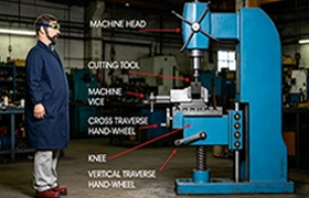
2. CNC Tool Deflection (The Precision Killer)
This is a “micro-bending” example. When a CNC milling machine is cutting a block of stainless steel, the cutting tool (the endmill) is under massive pressure.
- Manufacturing Example: The endmill acts as a cantilever beam. As it pushes into the metal, the tool actually bends backwards by a few microns. If we don’t calculate this “tool deflection,” the final part will be out of tolerance. This is why we use “stubby” tools for high-precision work—to increase the Moment of Inertia and reduce bending.
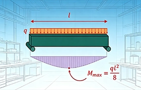
3. Simply Supported Beams (The Factory Gantry)
A beam supported at both ends.
- Manufacturing Example: The overhead gantry that moves a laser cutting head across a 10-foot table. The weight of the laser head causes the gantry rail to bend downward. If the gantry sags too much in the middle, the laser focus will change, resulting in a poor cut. We use wide-flange aluminum extrusions to ensure the rail stays perfectly flat across the entire span.
4. Sheet Metal Press Braking (Intentional Plastic Bending)
Not all bending is a failure. In sheet metal fabrication, bending is our primary tool.
- Manufacturing Example: Using a 100-ton press brake to force a flat sheet of aluminum into a 90-degree bracket. Here, we intentionally exceed the Yield Strength of the material to reach “Plastic Deformation”—where the metal permanently changes shape and stays bent.
5. Mandrel Tube Bending (Fluid Lines)
Bending a hollow tube is much harder than bending a solid bar because the tube wants to collapse or “kink” in the middle.
- Manufacturing Example: High-pressure hydraulic lines for industrial machinery. We use a “Mandrel” (a solid rod inserted into the tube) during the bending process to support the internal walls and prevent the cross-sectional area from shrinking.
Springback and the K-Factor
If you are a procurement manager, understanding these two terms will explain why some “cheap” shops return parts that don’t fit, while a professional shop gets it right the first time.
1. The Elastic Memory (Springback)
When we bend a piece of 6061-T6 Aluminum or 304 Stainless Steel on our press brakes, the metal does not simply “obey.” Metals are elastic by nature. When the heavy hydraulic punch pushes the metal into the die, the molecular structure on the outside curve stretches. However, those molecules want to return to their original position.
The moment the punch lifts, the metal “springs back” by several degrees.
- The Procurement Trap: If your designer draws a 90-degree bend, and the shop is inexperienced, they will bend the machine to 90 degrees. The part will spring back to 87 degrees. Your assembly won’t fit, and you’ve just wasted thousands of USD in scrap.
- The EPTAHUB Solution: We calculate the springback coefficient based on the material’s specific Yield Strength and the bend radius. To get a 90-degree finished part, we might intentionally over-bend the material to 93.5 degrees, allowing the “elastic memory” to snap the part back to a perfect 90.
2. The Stretching Logic (The K-Factor)
Here is a question that stumps many junior engineers: “If you bend a 10-inch flat plate, is the finished part still 10 inches long?”
The answer is No.
Because the outside of the metal stretches and the inside crushes, the physical length of the material actually changes. If we don’t account for this “Bend Allowance,” the holes you’ve drilled in your part will no longer line up with the mating component.
To solve this, we use the K-Factor. The K-Factor is a ratio that represents the location of the Neutral Axis (that zero-stress zone we talked about in Part 1) relative to the thickness of the material.
- Standard K-Factor: In most air-bending applications for cold-rolled steel, we use a K-Factor of roughly 0.44.
- Source Validation: These values are standardized in the Machinery’s Handbook (the “Bible” of the machine shop) and are used to calculate the “Flat Pattern” length before we ever touch a laser cutter.
Case Study: From Solid Machining to Bent Sheet Metal (Saving 38,400 USD)
At EPTAHUB, we don’t just take orders; we act as a fractional engineering team for our clients. Last year, a medical device startup approached us with a design for a specialized server chassis used in diagnostic imaging.
The Problem:
The original design called for the main structural frame to be CNC machined from a solid block of Aluminum 6061.

- Original Unit Cost: 425.00 USD per unit.
- Total Order (200 Units): 85,000 USD.
- The Issue: The design was incredibly heavy, and the lead time for 200 machined units was over 8 weeks.
The EPTAHUB Intervention:
Our engineering lead reviewed the CAD files and realized the part was primarily a “box” designed to support three internal circuit boards. The “bending moment” required to support these boards was relatively low. We proposed a “Sheet Metal Conversion.
We redesigned the frame to be manufactured from 5052-H32 Aluminum sheet (0.125-inch thickness).
- Structural Integrity: To maintain the stiffness of the original solid block, we added two “stiffening ribs” (intentional bends) along the primary axis. This increased the Area Moment of Inertia by over 400% compared to a flat sheet.
- Precision Engineering: We calculated a K-Factor of 0.42 to ensure that the mounting holes for the high-value circuit boards would align perfectly within a 0.005-inch tolerance after bending.
- The Result:
- New Unit Cost: 233.00 USD per unit.
- New Total Cost: 46,600 USD.
- Lead Time: 3 weeks.
The Outcome:
By understanding the physics of bending and the bending stress formula, we saved the client 38,400 USD on a single production run. The part was 60% lighter, easier to ship, and performed identically to the heavy machined version. This is the difference between “buying a part” and “engineering a solution.”
FAQ: Common Engineering Questions About Bending
Based on the most common queries we see at EPTAHUB, here are the hard-hitting engineering answers to the questions your procurement team is likely asking.
1. What is an example of a bending moment in real life?
A classic industrial example is a “Wall-Mounted Jib Crane.” When the crane arm reaches out to lift a pallet, the weight of the pallet (Force) multiplied by the distance from the wall (Distance) creates a massive bending moment at the wall mounting plate. If the bolts aren’t rated for that specific moment, they will shear off, even if they are rated for the pallet’s weight alone.
2. Is ceramic material plastic?
No. This is a common misconception in consumer-grade “materials 101” searches. Ceramics are inorganic, non-metallic solids. From a bending perspective, ceramics are “Brittle.” While a metal will experience “Plastic Deformation” (it will bend and stay bent), a ceramic will experience almost zero strain before it undergoes catastrophic “Brittle Fracture.” Ceramics cannot be “bent” in a press brake; they must be molded or machined into their final shape.
(Source Validation: ASTM C1161 – Standard Test Method for Flexural Strength of Advanced Ceramics).
3. What are the 4 types of strain associated with bending?
When an object bends, it experiences:
- Tensile Strain: Stretching on the outer radius.
- Compressive Strain: Crushing on the inner radius.
- Shear Strain: The internal layers of the material sliding against each other (often called “Interlaminar Shear”).
- Lateral Strain: Also known as the Poisson effect—when the top of the beam stretches, it also gets slightly thinner.
4. Can you calculate bending force for any material?
Yes, using the Bending Force Formula:
P=(k×T×L×t2)/W
Where P is the punch force, T is the material’s Tensile Strength, L is the length of the bend, t is the thickness, and W is the die width. At EPTAHUB, we use this to ensure our 100-ton press brakes aren’t being overloaded by high-strength alloys like AR400 or Titanium.
5. Why do my parts crack during the bending process?
This usually happens because the “Minimum Bend Radius” was ignored. Every material has a limit to how tightly it can be bent before the fibers on the outside curve (the tension side) simply tear apart. For most T6-temper aluminums, the internal bend radius should be at least equal to the thickness of the material. If you try to bend 1/4-inch 6061-T6 with a “sharp” 0.01-inch radius, it will crack 100% of the time.
Professional DFM Tips for Bending
If you want to keep your manufacturing costs low and your structural integrity high at EPTAHUB, follow these three rules:
Rule 1: The “Across the Grain” Rule
Just like wood, metal has a grain direction from the rolling process at the mill. Always design your parts so that the bend line is perpendicular to the grain. If you bend “with the grain,” the material is significantly more likely to crack.
Rule 2: Standardize Your Radii
Don’t design a part with five different bend radii. Every unique radius requires a different tool setup on the press brake. At EPTAHUB, setup time is one of the biggest drivers of NRE (Non-Recurring Engineering) costs. If you standardize your internal radii to a single common size (like 0.125 inches), we can run the entire part on one machine setup, saving you hundreds of USD in labor.
Rule 3: Use Relief Notches
When two bends meet at a corner, the metal has nowhere to go—it “bunches up” and creates a bulge that will prevent your part from fitting into its housing. By adding a small circular “Relief Notch” at the intersection of the bend lines, you allow the metal to move freely, resulting in a clean, professional corner.
Conclusion: Bending is the Science of Leverage
Whether you are looking for examples of bending in everyday life or trying to calculate the bending stress on a heavy-duty industrial chassis, the physics remains the same. Bending is a violent internal struggle between tension and compression, governed by the laws of leverage and the Area Moment of Inertia.
At EPTAHUB, we don’t just “bend metal.” We manage the invisible forces that determine the success or failure of your product. By understanding the bending moment formula, the reality of springback, and the importance of the K-Factor, you can transition from a designer to an engineer.
Don’t settle for a shop that just “hits the pedal” on the press brake. Choose a manufacturing partner that understands the metallurgy, the mathematics, and the economics of scale. Whether you need a single precision prototype or 10,000 mass-produced enclosures, we have the tools—and the math—to make it happen.