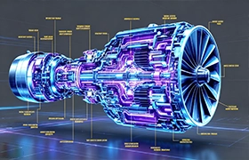
If you type “how does a jet engine work” into a search engine, you will inevitably be directed to a high school physics explanation: Suck, Squeeze, Bang, Blow. You will likely find a jet engine diagram simple enough for a child to understand, breaking the machine down into five neat, color-coded sections.
But if you are a procurement manager at a Tier-1 aerospace supplier, or a VP of Engineering at a commercial aviation OEM, you know that this textbook oversimplification is dangerously misleading.
At EPTAHUB, when an aerospace client sends us an RFQ (Request for Quote) containing .STEP files for turbine stators or compressor brackets, we aren’t looking at a simple diagram. We are looking at a manufacturing nightmare. We are looking at parts that must spin at 20,000 RPM while operating in environments that exceed the melting point of standard industrial metals. We are looking at components where a dimensional deviation of 0.0002 inches will cause a catastrophic, multi-million-dollar failure at 35,000 feet.
When B2B buyers search for “jet engine parts for sale,” they are not buying off-the-shelf catalog items. They are trying to source highly complex, custom-machined sub-components built from exotic superalloys that most machine shops refuse to touch.
If you are looking for a basic jet engine parts and function pdf, you are in the wrong place. If you want to understand why your aerospace Bill of Materials (BOM) costs 400,000 USD per engine assembly, keep reading.
Part 1: The Inlet and Fan (The Aerodynamic Funnel)
If you look at the front of a Boeing 777 or an Airbus A350, you are looking at the Fan and Inlet section. While early turbojet engine designs relied purely on exhaust thrust, modern high-bypass turbofans generate up to 80% of their total forward thrust simply by the massive front fan acting as a highly efficient propeller.
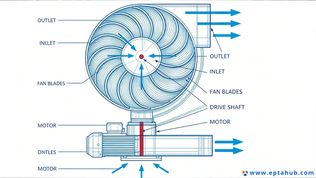
The Engineering Function
The primary job of the inlet is to capture turbulent ambient air and smooth it out into a uniform, subsonic flow before it hits the compressor. The massive fan blades grab this air and split it. A small portion (the core flow) goes into the engine itself, while the vast majority (the bypass air) is accelerated around the outside of the engine core to provide massive, fuel-efficient thrust and dampen engine noise.
The Manufacturing Reality: Machining the Fan Blades
When a layman looks at these massive front fan blades, they see curved metal. When I look at them, I see one of the most complex CNC milling operations on the planet.
1. The Material:
Historically, these blades were forged from solid blocks of Titanium Ti-6Al-4V. Titanium is notoriously difficult to machine. It has low thermal conductivity, meaning the heat generated by the cutting tool doesn’t dissipate into the metal chip—it stays in the tool, burning out expensive carbide endmills in minutes.
Today, to save weight, advanced OEMs use composite fan blades (Carbon Fiber Reinforced Polymers) with a precision-machined Titanium leading edge glued to the front to prevent the composite from shattering when the engine inevitably ingests a bird.
2. The 5-Axis Challenge:
Whether we are cutting a solid titanium blade or just the leading edge guard at EPTAHUB, these geometries require simultaneous 5-axis continuous CNC milling. The sweeping, twisted, aerodynamic curve of a fan blade cannot be machined by simply moving in X, Y, and Z. The machine head must twist and tilt continuously across the entire length of the blade to maintain a perfect perpendicular cutting angle.
The raw material cost alone for a single titanium forging can exceed 15,000 USD. If a machinist sets the work coordinate system incorrectly and gouges the part on the final finishing pass, that entire 15,000 USD block goes straight into the scrap bin.
Part 2: The Compressor (The Pressure Cooker)
Once the air passes the fan, it enters the core of the engine. If you reference any standard aircraft engine parts name directory, this section is universally known as the Compressor.
The Engineering Function
The goal here is simple but brutal: squeeze the air. The compressor is a series of alternating spinning blades (rotors) and stationary blades (stators). The air gets forced into a continuously shrinking physical space. By the time the air reaches the end of the High-Pressure Compressor (HPC), it has been squeezed down to 1/40th of its original volume, and the physical friction of this compression has heated the air to over 600°C (1,100°F)—and no fuel has even been added yet.
The Manufacturing Reality: Blisks and Broaching
The compressor section represents a critical transition zone in aerospace manufacturing. As the air moves deeper into the compressor, the temperature rises rapidly.
1. The Material Transition:
In the front (Low-Pressure Compressor), we can still use Titanium or high-grade Stainless Steel. But as we move to the rear (High-Pressure Compressor) where temps exceed 600°C, Titanium becomes a fire hazard (Titanium fires in jet engines are catastrophic). Here, we must transition to Nickel-based superalloys like Inconel 718. Inconel is notoriously “gummy” and work-hardens instantly as you cut it. It destroys cutting tools faster than almost any other metal on earth.
2. The Evolution of Blisks (Blade Integrated Disks):
Historically, compressor blades were manufactured individually. The root of the blade was machined into a “fir tree” or “dovetail” shape, and it was slid into a corresponding slot broached into a central titanium hub. Machining these complex fir tree roots requires highly specialized broaching machines that cost upwards of 2,000,000 USD, pulling a massive, multi-toothed cutting tool through the metal with tens of thousands of pounds of hydraulic force.
However, modern engine design is obsessed with weight reduction. Today, aerospace clients demand Blisks. A Blisk is a single, solid forging of Titanium or Inconel where the central hub and all 60+ compressor blades are machined out of one continuous piece of metal.
Manufacturing a Blisk at EPTAHUB requires weeks of continuous machining. We must plunge long, thin cutting tools deep between the blades to carve out the airflow channels. Because the tools are long and thin, they are prone to vibration (chatter), which leaves a poor surface finish. To counter this, we utilize adaptive CAM software that dynamically slows the feed rate when it senses resonance, ensuring the final Ra (surface roughness) is aerodynamically flawless.
Part 3: The Combustor (Controlled Hellfire)
If you are a procurement manager looking at a breakdown of aircraft engine parts and functions, the Combustor (or Combustion Chamber) is where the physics of the engine shift from aerodynamics to extreme thermodynamics.
The Engineering Function
The intensely pressurized, 600°C air exits the compressor and enters the combustor. Here, highly atomized jet fuel (Jet-A) is injected into the airstream and ignited. The resulting continuous explosion expands the gases violently.
The engineering problem is terrifying: the temperature inside the combustor burns constantly at over 2,000°C (3,600°F). However, the metal walls of the combustor itself have a melting point of roughly 1,300°C to 1,400°C.
Let me repeat that for clarity: The fire inside the engine is 600 degrees hotter than the melting point of the metal holding the fire. If you do not engineer this correctly, the combustor will vaporize in seconds.
The Manufacturing Reality: Cooling Holes and EDM
You cannot solve the Combustor problem with standard CNC milling. The metals used here (typically Hastelloy X, Haynes 188, or Nimonic alloys) are incredibly tough, but they cannot survive 2,000°C ambient temperatures. We survive this environment using a combination of microscopic air conditioning and advanced surface chemistry.
1. The “Film Cooling” Matrix:
To prevent the combustor walls from melting, we must surround them in a protective blanket of cooler bypass air. To do this, the combustor liners are perforated with thousands of microscopic, angled cooling holes.
You cannot drill these holes with a mechanical drill bit. The nickel alloys are too hard, and the bits would snap instantly at the required angles. At EPTAHUB, we utilize Sinker EDM (Electrical Discharge Machining) and 5-Axis Laser Drilling. We use high-voltage electrical sparks or focused industrial lasers to literally vaporize the holes through the metal, one by one. The angle of these holes is hyper-critical; they are designed to force the cooling air to “stick” to the inside wall of the combustor, creating a boundary layer of cool air that physically separates the metal from the 2,000°C fire.
2. Thermal Barrier Coatings (TBCs):
Even with microscopic cooling holes, the metal needs armor. After the combustor liners are machined and welded, they are sent to specialized vacuum chambers. Here, a robotic arm uses plasma spray to coat the inside of the liner with a highly advanced Ceramic (usually Yttria-Stabilized Zirconia). As discussed in our previous ceramics guide, this material is a phenomenal thermal insulator. A coating less than a millimeter thick can drop the temperature experienced by the underlying metal by over 150°C.
When a client wants to know why a single combustor liner segment costs 25,000 USD, it is because we are paying for 5-axis laser drilling of 10,000 microscopic holes, followed by vacuum plasma ceramic deposition.
Part 4: The Turbine (The Mechanical Powerhouse)
If the compressor is the lungs of the engine, and the combustor is the heart, the Turbine is the muscle. When you review a what are the 5 major parts of an engine pdf, the Turbine is often the most misunderstood section. Many assume it simply pushes air out the back. It does not.
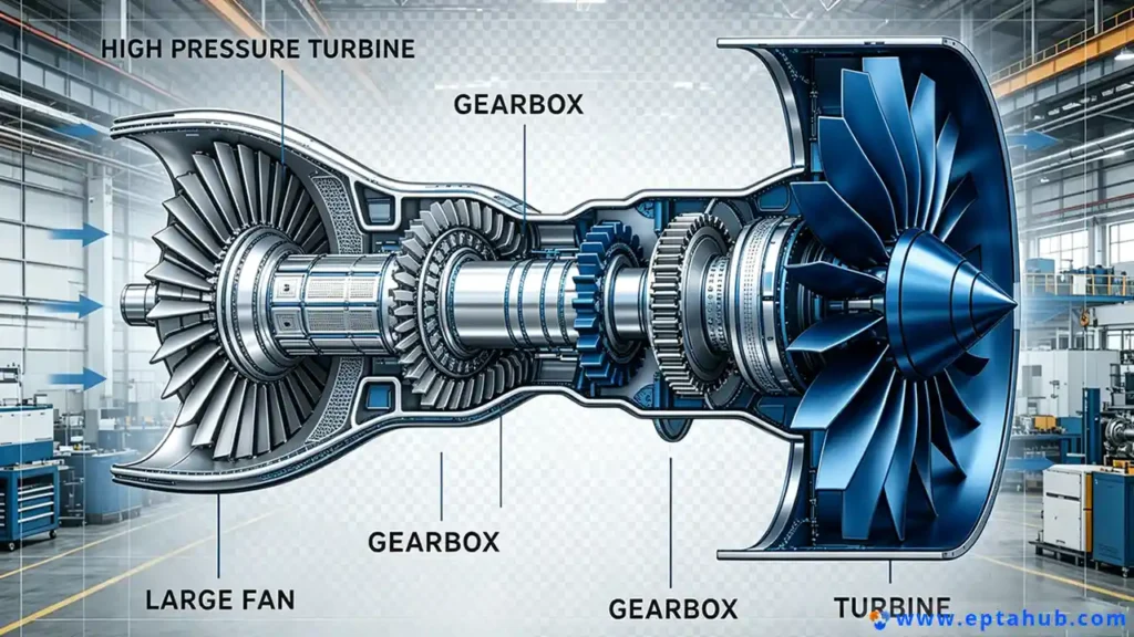
The Engineering Function
The violently expanding gases blast out of the combustor and slam into the blades of the High-Pressure Turbine (HPT). The sole purpose of the turbine is to capture the kinetic energy of this exhaust gas and convert it into mechanical rotational energy. The turbine is bolted directly to the central shaft of the engine, which spins the compressor and the massive fan at the front.
Without the turbine extracting energy, the engine cannot suck in new air, and the entire cycle dies.
The Manufacturing Reality: Single-Crystal Superalloys
The High-Pressure Turbine (HPT) blades operate in the most hostile mechanical environment devised by mankind. They are subjected to the direct 2,000°C exhaust of the combustor, while simultaneously spinning at 20,000 RPM. The centrifugal force is so immense that each individual blade, weighing less than a pound, exerts a pulling force equivalent to the weight of a commercial pickup truck on the turbine disk hub.
If you machine a turbine blade from standard cast or forged metal, the microscopic grain boundaries (the seams where individual metal crystals meet) will literally tear apart under the heat and stress—a failure mode called “creep.”
1. The Single-Crystal Casting Miracle:
To survive this, modern HPT blades are not CNC machined from solid blocks. They are cast. But they are not cast normally. Aerospace foundries use a proprietary investment casting process to grow the entire turbine blade out of one single, continuous, flawless metal crystal of an advanced Rhenium-doped Nickel superalloy. Because there are no microscopic grain boundaries in a single-crystal blade, there are no weak points for the heat and centrifugal force to exploit.
2. Internal Cooling Labyrinths:
Just like the combustor, the turbine blades operate well above their melting point. But you cannot simply laser-drill holes straight through a solid blade, because you need the air to circulate inside the blade first.
Before the single-crystal casting is poured, an incredibly intricate ceramic core (shaped like a 3D maze) is placed inside the mold. Once the superalloy cools and solidifies, the ceramic core is chemically leached out using hydrofluoric acid. This leaves behind a hollow, maze-like cooling labyrinth inside the solid metal blade. Cooler air from the compressor is routed through the central shaft, forced up inside the hollow turbine blade, snakes through the internal labyrinth to cool the metal from the inside out, and then bleeds out of laser-drilled holes on the blade’s leading edge to provide external film cooling.
When an OEM sends EPTAHUB a CAD file for a turbine disk assembly, they are sending us geometries that require the absolute pinnacle of human manufacturing capability. The scrap rate on single-crystal castings alone makes these parts some of the most expensive individual components in modern engineering.
Part 5: The Exhaust / Nozzle (The Thrust Vector)
We have reached the end of the traditional what are the 5 parts of a jet engine textbook list. After the turbine has extracted enough energy to spin the compressor and the front fan, the remaining exhaust gas must be efficiently expelled.
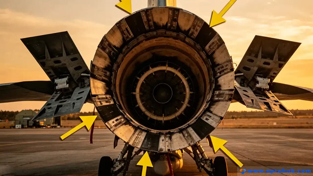
The Engineering Function
The exhaust section (or nozzle) acts as a high-velocity funnel. Its job is to manage the expansion of the exhaust gases, straightening the turbulent flow and accelerating it out the back of the engine to provide the final 20% of the forward thrust. In military applications, this nozzle is often highly complex, featuring “thrust vectoring” paddles that physically tilt the exhaust stream to allow fighter jets to perform physically impossible maneuvers. In commercial aviation, the nozzle includes the thrust reverser mechanisms used to slow the aircraft down upon landing.
The Manufacturing Reality: Sheet Metal and Honeycomb Core
Unlike the solid, forged, and milled components of the compressor, the exhaust section relies heavily on advanced sheet metal fabrication and structural composites.
1. Titanium Honeycomb Structures:
Because the exhaust nozzle is massive but needs to be incredibly lightweight, we cannot use thick plates of steel or nickel. Instead, at EPTAHUB, we utilize brazed honeycomb structures. We take two incredibly thin sheets of Titanium or Inconel and braze them to a central core of metal shaped exactly like a bee’s honeycomb. This creates a panel that is 90% hollow air, yet possesses the structural rigidity of a solid metal plate half an inch thick.
2. Acoustic Attenuation:
If you look closely at the inside of the exhaust nozzle (and the front inlet) on a modern airliner, you will see thousands of tiny holes. This is not for cooling; this is acoustic attenuation. The noise generated by the shearing of the high-speed exhaust against the slower ambient air is deafening. These microscopic holes act as Helmholtz resonators, trapping specific frequencies of sound waves and canceling them out before they leave the engine casing, ensuring the engine meets strict FAA noise regulations.
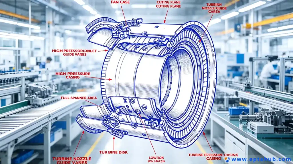
The Unspoken 6th Part: The Engine Casing and Mounts
When procurement teams search for “what are the six major engine sections?”, they are usually correcting the simplified 5-part model by adding the structural backbone of the entire assembly: The Casing.
All the thermodynamic violence we just discussed—the 20,000 RPM shafts, the 2,000°C fires, the massive centrifugal loads—must be safely contained inside a metal tube and bolted to the wing of the aircraft.
The Manufacturing Reality: Machining the Casing
The engine casing is typically manufactured from massive, thin-walled forgings of Titanium (front) and Inconel (rear).
The challenge here is dimensional stability. When we machine a casing ring that is 10 feet in diameter but only 0.250 inches thick, the metal wants to warp, spring, and deform the moment we remove material.
To hold tight circularity tolerances, we cannot simply clamp the part in a standard lathe jaw; the clamping force alone would crush the casing into an oval. We must design massive, custom-built, vacuum-assisted workholding fixtures that cost upwards of 80,000 USD just to hold the part gently enough to machine it, but securely enough that it doesn’t tear out of the machine when the cutting tool engages. Furthermore, the casing must pass “blade containment” tests. If a titanium fan blade snaps off at full speed, the casing must be engineered to physically catch and contain the shrapnel, preventing it from slicing through the passenger cabin.
Aerospace Quality Control: How EPTAHUB Certifies Flight-Critical Parts?
In aerospace manufacturing, making the part is only 50% of the job. Proving to the FAA (Federal Aviation Administration) and the OEM that you made it correctly is the other 50%. The paperwork often weighs more than the metal.
If you are sourcing jet engine components, you must ensure your manufacturing partner is certified to AS9100D (the rigorous aerospace quality standard). At EPTAHUB, our QA department utilizes a triple-threat inspection protocol for high-stress turbine and compressor parts:
- FPI (Fluorescent Penetrant Inspection):
You cannot see microscopic surface cracks in Titanium with the naked eye. We submerge the machined parts in a highly penetrating fluorescent dye, wash them off, and inspect them under ultraviolet (UV) blacklight in a dark room. Any microscopic crack will trap the dye and glow bright green, resulting in immediate scrap. - Digital Radiography (X-Ray):
For cast parts, such as turbine blades, FPI is not enough because it only checks the surface. We must place the parts in industrial X-ray machines to look for internal voids, porosity, or inclusions (foreign debris) hidden deep inside the metal wall. - CMM (Coordinate Measuring Machine) Scanning:
A turbine blade’s complex 3D aerodynamic profile cannot be measured with calipers. We use ultra-precise CMM touch probes and non-contact blue-light laser scanners to generate a digital 3D point cloud of the finished part, overlaying it onto the original CAD file to ensure every micrometer of the aerodynamic curve is within the +/- 0.0005 inch tolerance band.
EPTAHUB Case Study: The Cost of Over-Engineering
A common issue we see when startups try to build drone or small-scale turbine engines is over-specifying materials.
The Problem: A client sent us an RFQ for a small, stationary compressor stator ring for an APU (Auxiliary Power Unit). The engineer had specified Inconel 718 for the part, assuming “it goes in a jet engine, it must be Inconel.” The quote came out to 4,200 USD per part, primarily due to the abysmal machining speeds required for Inconel.
The EPTAHUB Solution:
During our DFM (Design for Manufacturing) review, we analyzed the actual operating temperatures of the specific compressor stage the part was located in. The ambient temperature for that specific stator never exceeded 400°C.
I immediately kicked the .STEP file back to their engineering team and advised them to downgrade the material to 17-4 PH Stainless Steel (Condition H900). 17-4 PH possesses phenomenal yield strength and easily survives 400°C environments, but it machines roughly 400% faster than Inconel.
The ROI:
By trusting our manufacturing engineering expertise and correcting their material selection, the client’s unit cost dropped from 4,200 USD down to 950 USD per part, with absolutely zero loss in performance or safety margins. That is the value of partnering with a manufacturer who understands the physics behind the CAD file.
Authoritative Engineering References
For procurement managers and engineers looking to dive deeper into the metallurgical standards and geometric tolerancing required for the 5 main parts of a jet engine, refer to these industry-standard resources:
1.FAA – Advisory Circulars (AC 33-2B)
The legal guidelines dictating how aircraft engines are tested for endurance, blade containment, and bird ingestion before they are allowed to fly over populated areas.
Link: FAA.gov
2.ASME Y14.5 – Geometric Dimensioning and Tolerancing (GD&T)
Aerospace blueprints do not use simple +/- dimensions. They use complex geometric datums to control profile, runout, and concentricity. This standard is mandatory reading for anyone programming CNC toolpaths for turbine components.
Link: ASME.org