If you walk onto the factory floor at EPTAHUB and ask a junior operator, “What does a CNC milling machine do?”, they will probably tell you, “It cuts metal.”
If you ask me, a manufacturing engineer who has spent the last 12 years calculating cycle times and quoting aerospace components, my answer is a bit different: A CNC milling machine converts raw stock into highly precise, repeatable profit.
In the B2B hardware space, there is a massive disconnect between the engineers designing the CAD files in an air-conditioned office and the procurement teams trying to buy those parts. We see Requests for Quote (RFQs) every day where a designer has requested a complex geometry that requires a 500,000 USD 5-axis milling center, when a simple redesign would allow us to run it on a basic 3-axis machine for a fraction of the cost.
To stop burning your company’s capital, you need to understand exactly what happens inside the machine enclosure. You need to understand the CNC milling process.
What CNC Milling Stands For?
To understand the machine, you have to decode the acronym. What does CNC milling stand for?
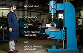
- CNC (Computer Numerical Control): In the 1960s, machinists had to manually turn handwheels to move the cutting tool across the metal. Today, a computer brain reads a program (called G-Code) and directs servo motors to move the machine components with microscopic precision.
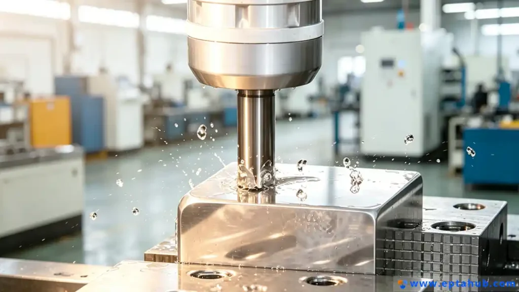
- Milling: This is the specific mechanical process of Subtractive Manufacturing. In milling, the raw block of material (the workpiece) is held completely stationary in a heavy steel vise. The cutting tool (the endmill) rotates at incredibly high speeds (often 10,000 to 30,000 RPM) and drives into the stationary metal, shearing away chips of material until only the final shape remains.
Source Validation: The foundational definition of Computer Numerical Control and subtractive milling processes is universally standardized and documented in the Machinery’s Handbook (the definitive reference manual for the mechanical industry).
The Main Purpose of CNC Machines
When a procurement manager searches for “What is the main purpose of CNC machines?”, the answer boils down to three industrial pillars:
- Tolerance (Accuracy): A quality CNC mill at EPTAHUB can hold tolerances of +/- 0.0005 inches (roughly a fraction of the width of a human hair). You cannot achieve this with casting, and you certainly cannot achieve it with 3D printing.
- Material Integrity: Unlike 3D printing (which melts and stacks plastic or metal, creating weak points between layers), CNC milling cuts from a solid block of extruded or forged metal (like 6061-T6 Aluminum or Grade 5 Titanium). The final part retains 100% of the raw material’s original tensile and yield strength.
- Repeatability (Mass Production): Once the G-Code is proven, the machine will make part number 1 and part number 10,000 exactly the same.
The 5 Main Uses (Types of CNC Milling Operations)
If you look at a complex aerospace bracket, it wasn’t made in one single motion. It was made through a series of distinct types of CNC milling operations. As a buyer, you need to understand these five operations, because each one requires a different tool and adds a different amount of time to your final quote.
1. Face Milling (Establishing the Datum)
When we buy raw aluminum or steel bar stock from the mill, it is not perfectly flat. It is bowed, scratched, and rough. The very first operation we perform is Face Milling. We take a large-diameter tool (often 2 to 4 inches wide) with carbide inserts and sweep it across the top of the raw block. This creates a perfectly flat, mirror-like surface.
- Engineering Value: This flat surface becomes the “Datum” (the zero reference point) for all other dimensions on your CAD drawing.
2. Profile Milling (Cutting the Perimeter)
Once the top is flat, we need to cut the outside shape of your part. We use an endmill to trace the exterior boundary of the CAD model, stepping down slightly with each pass until we reach the bottom of the material.
- The Cost Trap: If your designer creates a part that is 3 inches tall, but the design requires us to profile the entire outside wall all the way down, we have to use a very long cutting tool. Long tools vibrate (chatter), which forces us to run the machine much slower. Slower machine time equals higher USD cost per part.
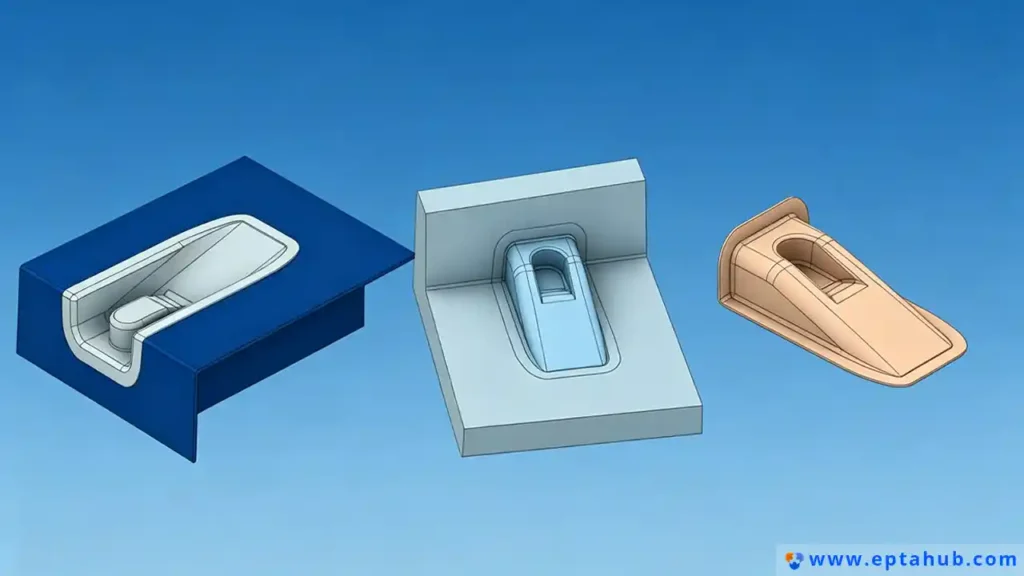
3. Pocket Milling (The Material Hog)
If your part looks like a shallow box, an enclosure, or a tray, we have to hollow out the inside. This is called Pocketing. At EPTAHUB, pocketing usually accounts for the majority of the cycle time.
To do this efficiently, we use a technique called HEM (High-Efficiency Machining). Instead of taking slow, heavy cuts, we run the tool incredibly fast but take very thin “peels” of metal. This prevents the tool from snapping and throws all the heat into the metal chip rather than the part.
- Source Validation: High-Efficiency Machining (HEM) and chip-thinning calculations are industry-standard toolpath strategies validated by leading cutting tool manufacturers like Harvey Tool and Sandvik Coromant.
4. Drilling and Tapping (Hole Making)
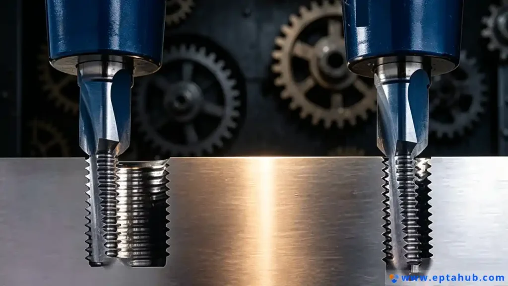
This is exactly what it sounds like. The machine grabs a drill bit to plunge holes into the part. Then, it grabs a Tap (a threading tool) to cut internal threads so you can bolt the assembly together.
- DFM Tip for Buyers: Never design a threaded hole that goes deeper than 3 times the diameter of the bolt (e.g., a 1/4-inch bolt should not go deeper than 0.75 inches). Tapping deep holes is the number one cause of broken tools, which will stall the machine and spike your setup costs.
5. 3D Surface Milling (Complex Contouring)
If you are manufacturing a plastic injection mold, or a specialized medical implant that matches human bone, the surfaces are not flat—they are swooping, organic, 3D curves. We use a “Ball Endmill” (a tool with a spherical tip) and command the machine to move the X, Y, and Z axes simultaneously. The tool steps over by tiny fractions of an inch (often 0.005 inches at a time) to slowly sweep across the geometry.
- The Reality: 3D surfacing takes hours. If your part does not absolutely need a curved surface for aerodynamic or ergonomic reasons, remove it. Flat 2D features will slash your unit cost in half.
CNC Milling vs Turning
A very common point of confusion for procurement teams sourcing new vendors is the difference between milling and turning. A search for “CNC milling vs turning” usually yields overly academic answers.
Here is the B2B factory floor reality:
- CNC Milling (The Mill): The raw material is bolted down and does not move. The cutting tool spins. We use Mills for square parts, rectangular blocks, complex aerospace brackets, and electronic enclosures.
- CNC Turning (The Lathe): The raw material is gripped in a chuck and spins at high speeds (like a potter’s wheel). The cutting tool is bolted down and does not spin; it simply pushes into the spinning metal to shave it down. We use Lathes for cylindrical parts: shafts, pins, custom washers, and round aerospace flanges.
Why does this matter to you?
Turning is almost always faster and cheaper than milling. If you design a part that is cylindrical, we can turn it on a Lathe in 45 seconds for 3.00 USD. If you design that same cylindrical part but put a square flange on the bottom of it, it can no longer be turned on a standard Lathe. It must be moved to a Mill. That 45-second cycle time just jumped to 6 minutes, and the cost just jumped to 18.00 USD.
Always design for the Lathe if the geometry allows it. If it must be a complex, asymmetric shape, then you send it to the Mill.
What Are the Cons of CNC Milling?
When I consult with hardware founders who are trying to transition from 3D printed prototypes into mass production, they often view CNC machining as the ultimate, flawless manufacturing method. While it is true that CNC milling offers unmatched precision and material strength, it is not magic.
As a procurement manager, you must understand the limitations—the cons of CNC milling—before you commit your budget.
1. High Initial Setup and NRE Costs (The “One-Off” Penalty)
CNC milling is not a “print-on-demand” process. Before a single chip of metal is cut, a programmer must import your CAD file, write the CAM toolpaths, select the physical cutting tools, load them into the machine carousel, indicate the tools for length, cut raw stock on a bandsaw, and set up the workholding vise.
This entire process (Setup and Non-Recurring Engineering) can take anywhere from 2 to 6 hours. If the shop rate is 100 USD per hour, you have accumulated 600 USD in labor costs before the machine even starts.
- The B2B Lesson: If you only order 1 part, that part costs 600 USD plus machine time. If you order 1,000 parts, that 600 USD setup fee amortizes down to just 0.60 USD per part. CNC milling is highly cost-prohibitive for extreme low-volume production, but becomes incredibly economical at scale.
2. Geometry Limitations (The Inside Corner Problem)
Because CNC milling uses a spinning, cylindrical tool to remove metal, it is physically impossible to cut a perfectly sharp, 90-degree internal corner.
Imagine trying to push a round coin into the corner of a square room; there will always be an unfillable gap. In CNC milling, every internal pocket or corner will have a radius that corresponds to the size of the cutting tool.
If your CAD designer insists on perfectly sharp internal corners, we are forced to use secondary operations like EDM (Electrical Discharge Machining) or broaching, which will immediately double the cost of your part.
3. High Material Waste (The Subtractive Nature)
CNC milling is subtractive. To make a 2-pound aerospace bracket, we might have to start with a 10-pound block of solid aluminum. We are literally turning 8 pounds of expensive raw material into scrap chips. While those chips can be recycled, you are still paying the upfront cost for the raw material weight. If you are machining exotic materials like Inconel or Grade 5 Titanium, this material waste can severely impact your unit economics.
Source Validation: The geometric limitations of rotating cutting tools (the internal radius problem) and the high material waste associated with subtractive manufacturing are fundamental laws of mechanical engineering, taught in every DFM (Design for Manufacturing) curriculum globally, including standards published by ASME (American Society of Mechanical Engineers).
Is CNC Milling Easy to Learn?
A common Google search among operations managers trying to bring manufacturing in-house is: “Is CNC milling easy to learn?” and “Is CNC milling a good career?”
There is a dangerous misconception in the modern tech sector that because a CNC machine is controlled by a computer, anyone can walk up, press a green button, and make a part. This is fundamentally false.
Operator vs. Machinist vs. Programmer
To understand how hard it is to learn, you must understand the hierarchy of the factory floor:
- The Button Pusher (Operator): Learning to load a block of metal into a vise, close the door, and press the green “Cycle Start” button is very easy. You can teach a high school student to do this in three days. However, if the machine makes a strange noise, or the tool breaks, the operator has no idea how to fix it.
- The Setup Machinist: Learning to read a complex blueprint, select the right workholding, indicate a vise so it is perfectly straight within 0.0001 inches, and adjust tool offsets to keep the part in tolerance takes 2 to 5 years of dedicated apprenticeship.
- The CAM Programmer: Learning to look at a 3D CAD model, calculate the exact speeds and feeds (RPM and feed rate) for different metals, and write the G-Code toolpaths that will cut the part efficiently without crashing the 500,000 USD machine takes 5 to 10 years of intensive engineering experience.
So, is it easy to learn? No. True CNC machining is applied physics. You are dealing with metallurgy, thermal dynamics, harmonic vibration (chatter), and advanced trigonometry. This steep learning curve is precisely why skilled CNC machinists are highly paid, and why bringing CNC milling in-house is usually a financial disaster for startups that underestimate the talent required.
This is why hardware companies rely on EPTAHUB. You are not just paying for access to our machines; you are paying for the decades of collective engineering experience required to make those machines run flawlessly.
The EPTAHUB Case Study: The Cost of Over-Engineering
To bring all these concepts together, let’s look at a real-world scenario that illustrates the true CNC milling cost and the importance of understanding the process.
Last year, a robotics automation company came to EPTAHUB with an RFQ for 500 units of a primary structural chassis for an autonomous warehouse robot.
The Problem: The “Desktop CAD” Mindset
The client’s engineering team had designed the chassis as one massive, monolithic block of 6061-T6 Aluminum. The part was 24 inches long, 18 inches wide, and had deep, hollowed-out pockets on all six sides.
Because it had complex features on all six faces, it required a 5-Axis CNC Milling Center. Furthermore, because it started as a massive 150-pound block of aluminum, the material costs were astronomical. We were going to spend 14 hours machining away 130 pounds of chips just to leave a 20-pound frame.
The initial quote for this part was 2,800 USD per unit. The client’s procurement team rejected the quote, stating it would bankrupt the project.
The Solution: DFM and Assembly
Our engineering team at EPTAHUB stepped in to perform a DFM (Design for Manufacturing) overhaul. We educated the client on the very principles discussed in this guide.
Instead of machining one massive block on a 5-Axis mill, we redesigned the chassis into four separate, flat plates that could be bolted together.
- Machine Downgrade: Because the parts were now flat 2D plates, we didn’t need the 500,000 USD 5-Axis machine. We could run them on our standard, high-speed 3-Axis Vertical Milling Centers, which have a much lower hourly shop rate.
- Material Savings: We bought standard thickness aluminum plate stock. The material waste dropped from 130 pounds of chips down to just 15 pounds of chips.
- Operation Speed: We utilized standard Face Milling and Profile Milling operations with large, rigid tools. The cycle time plummeted.
The Outcome
By understanding how a CNC mill actually removes material, we reduced the manufacturing time by 75%.
The new unit cost for the four-plate assembly dropped from 2,800 USD down to 485 USD. We successfully delivered the 500 units, saving the client over 1,150,000 USD on their production run.
FAQ: Questions About CNC Milling Operations
1. What is the average cost of CNC?
This is the most common, yet impossible to answer, question in manufacturing. CNC milling is not priced by the pound; it is priced by time. If you have a simple aluminum block with four drilled holes, it might cost 15 USD. If you have a complex titanium aerospace impeller that requires 12 hours of 5-Axis milling, it might cost 4,000 USD. The only way to get an accurate cost is to submit a STEP file to EPTAHUB for a formal cycle-time analysis.
2. Can CNC mills cut hardened steel?
Yes. While most people associate CNC machining with softer metals like aluminum or brass, modern CNC mills equipped with rigid spindles and specialized ceramic or coated-carbide endmills can easily “hard mill” tool steels (like D2 or H13) that exceed 55 HRC (Rockwell Hardness). This is how injection molds are manufactured.
3. What is a “setup” in CNC milling?
A “setup” refers to the orientation of the part in the machine. A standard 3-axis mill can only cut the top face of the material. If your part has holes on the bottom, the machine must stop, the operator must open the doors, unclamp the part, flip it upside down, re-clamp it, and run a second program. This is called “Setup 2.” Every time a human has to touch the part to flip it, your unit cost increases. Good design minimizes setups.
4. Why does CNC milling use coolant?
When you drag a carbide tool through solid steel at 10,000 RPM, the friction generates massive amounts of heat. If left unchecked, this heat will weld the metal chips to the tool, snapping the cutter instantly. The machine floods the cutting zone with a high-pressure mixture of water and synthetic oil (coolant). This serves two purposes: it rapidly cools the tool, and it forcefully flushes the metal chips out of the pocket so the tool doesn’t re-cut them.
Conclusion: Stop Guessing, Start Engineering
Understanding what a CNC milling machine does is not just an academic exercise. For procurement managers, hardware founders, and supply chain executives, it is a critical financial survival skill.
Every CAD feature your team designs—every deep pocket, every sharp internal corner, every exotic material choice—translates directly to spindle time, tooling wear, and USD costs on the factory floor.
The era of tossing a CAD file over the wall to a machine shop and hoping for a good price is over. To survive in the modern B2B hardware market, you must design specifically for the subtractive milling process. You must embrace standard tooling, minimize your setups, and utilize flat datums.
If your current suppliers are just sending you exorbitant quotes without explaining the “why,” you are working with the wrong partners.
At EPTAHUB, we do not just push buttons and cut metal. We bridge the gap between your engineering office and our factory floor. We dissect your CAD files, apply rigorous DFM principles, and optimize the toolpaths to ensure that when our CNC mills start running, they are producing maximum value for your supply chain.
Stop letting poorly optimized designs dictate your budget. Submit your 3D files to EPTAHUB today, and let our engineering team show you how CNC milling is actually supposed to work.