Almost every week at EPTAHUB, an enthusiastic product designer will email me a link to a file they found on Thingiverse or a basic shape they modeled in Tinkercad. The email usually says something like: “Here is the file. We need 50 of these in nylon. Can you hit print today?”
This mindset comes from the 2D paper printing world. When you want to print a PDF on a standard office printer, you just hit Ctrl+P. The computer and the printer handle the translation automatically in the background.
Because of this, people frequently ask me: “Can you 3D print without a slicer?” or “Can you print an STL without slicing?”
The answer is an absolute, uncompromising no.
If you take an STL or STEP file and put it directly on a USB drive, and plug that drive into a 500,000 USD industrial SLS (Selective Laser Sintering) machine, the machine will do nothing. The printer does not understand 3D shapes. It is completely blind to your CAD model.
To turn a digital idea into physical reality, you have to run it through a translation engine. That engine is the slicer.
In this guide, I am going to explain exactly what is slicing in 3D printing and why it is important. I will walk you through the math behind the slicing algorithms, explain why your software settings determine the physical strength of your parts, and show you why the slicer is where the real engineering happens.
What is Slicing in 3D Printing?
To understand why a slicer is mandatory, you have to understand the physical limitations of a 3D printer.
Whether we are talking about a desktop FDM machine or an industrial metal printer at EPTAHUB, additive manufacturing machines can only build objects in one specific way: from the bottom up, one microscopic layer at a time.

When you ask, “What is slicing in 3D printing?”, you are asking about the CAM (Computer-Aided Manufacturing) phase of the process.
A slicer is a specialized piece of software that imports your 3D digital model and literally cuts it horizontally into hundreds or thousands of flat, 2D cross-sections.
Once it has chopped your model into these flat slices, the 3D printing slicing algorithm calculates the exact path the printer’s mechanical components must take to draw that specific layer. It converts those physical paths into G-Code—a programming language consisting of X, Y, and Z coordinates, extrusion rates, and temperature commands.
Source Validation: The concept of slicing as a necessary precursor to additive manufacturing is formally defined in ISO/ASTM 52900:2021 (Additive manufacturing — General principles — Terminology), which dictates that 3D geometries must be sliced into planar layers to generate toolpaths.
What is Layering in 3D Printing?
If you want to know what is layering in 3d printing, hold a deck of playing cards in your hand.
If you look at the deck from the top, it looks like a solid 3D rectangular block. But if you look closely at the side, you see that the “block” is actually just 52 flat 2D layers stacked on top of each other.
This is exactly what the slicer does to your CAD file. If you send me a design for a 1-inch tall cylinder, and we set our slicer to a layer height of 0.1 millimeters, the slicer will cut that cylinder into 254 individual, flat circles. The printer will print circle #1, move the Z-axis up by 0.1mm, print circle #2 directly on top of it, and repeat that process 252 more times until the solid cylinder is formed.
Why Slicing is Important: The Illusion of Solid CAD
Now we get to the core of the issue. Why can’t the printer just do this automatically? Why do we need dedicated slicing software like Prusa Slicer, UltiMaker Cura, or high-end industrial programs like Materialise Magics?
Because a CAD file is a liar.
When you draw a solid cube in your CAD software, the computer treats it as a 100% solid block of plastic or metal. But in the real world of manufacturing, printing a 100% solid block of plastic is usually a terrible idea. It wastes material, it takes forever to print, and as the massive volume of plastic cools, the thermal contraction will cause the part to warp and rip itself off the build plate.
When you import that “solid” cube into the slicer, the slicer strips away the inside. It makes the part completely hollow. It is now up to the manufacturing engineer to use the slicer settings to build the internal physics of the part.
Here are the critical engineering decisions we make inside the slicer at EPTAHUB:
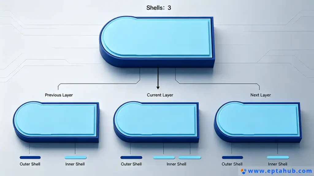
1. Perimeters (The Shell)
The first thing we tell the slicer is how thick the outside walls of your part should be. We call these “perimeters” or “shells.”
If you are prototyping a cosmetic enclosure that just needs to sit on a desk and look pretty, we might tell the slicer to only print 2 perimeters (making a wall roughly 0.8mm thick). It will print incredibly fast and cost very little USD.
But if you are printing a structural bracket that needs to hold a 50-pound motor, we will tell the slicer to print 6 or 8 perimeters. The thicker the shell, the higher the impact resistance.
2. Infill Density and Pattern (The Internal Skeleton)
Since we aren’t printing the part 100% solid, we have to support the empty space inside the shell. This is called infill.
The slicer allows us to automatically generate an internal geometric skeleton. We can choose the density (e.g., 20% infill means the inside is 20% plastic and 80% empty air). We can also choose the pattern.
- Grid/Rectilinear Infill: Fast and standard, good for basic top-load compression.
- Gyroid Infill: A complex, undulating 3D wave pattern that provides equal shear strength from all directions. We use this heavily at EPTAHUB for end-use functional parts because it prevents catastrophic failure if the part is twisted or dropped.
Source Validation: Studies on the mechanical properties of FDM printing, such as those published in the Journal of Manufacturing Processes, consistently show that altering the infill pattern (specifically moving from 2D grids to 3D structures like Gyroid) significantly alters the tensile and flexural strength of printed polymers without adding material weight.
3. Temperature and Flow Dynamics
The slicer doesn’t just manage geometry; it manages thermodynamics.
People often ask, “Why is PLA a popular choice for 3D printing?” The answer is largely because PLA has a very forgiving temperature window. It melts easily around 200°C and doesn’t warp significantly when it cools.
But if we are slicing an engineering-grade material like Polycarbonate or Nylon-Carbon Fiber, the slicing algorithm must be heavily manipulated. We have to program the slicer to tell the nozzle to extrude the plastic at exactly 280°C, command the heated bed to stay at 110°C, and completely turn off the cooling fans so the ambient air doesn’t shock the plastic and cause layer delamination.
If you get these slicer settings wrong, your part will literally tear itself apart before it finishes printing.
The Battle Against Gravity: Supports and Rafts
If you hold your arm straight out to the side, your arm is defying gravity. In the 3D printing world, we call this an “overhang.”
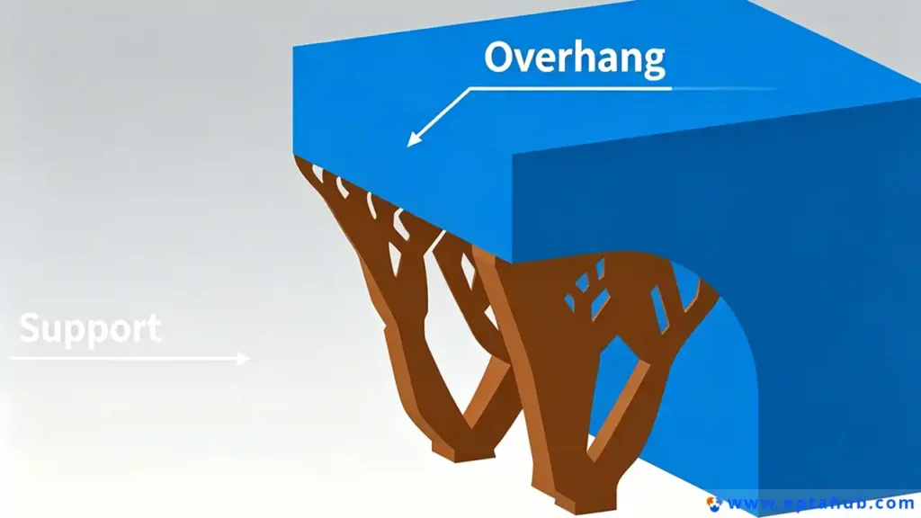
Because additive manufacturing works by stacking layers from the bottom up, you cannot print plastic in mid-air. If your CAD design has an overhang that extends out horizontally (like the roof of a house or the arm of a figurine), the printer nozzle will literally be extruding molten plastic into thin air. The plastic will fall to the build plate, and the print will fail catastrophically in a mess of tangled plastic string.
This is where the slicer proves its true value. It mathematically predicts gravity.
Intelligent Support Structures
When we run a complex geometry through our slicing software at EPTAHUB, the algorithm analyzes every single digital layer. It identifies any geometry that overhangs at an angle greater than roughly 45 degrees.
The slicer then automatically generates support structures—temporary, scaffolding-like towers that build up from the build plate to hold the overhanging geometry in place while it prints.
In high-end slicing, this isn’t just a basic grid. Modern slicing algorithms use “Tree Supports,” which grow organically from the build plate around the model, using minimal material while providing maximum stability. Once the print is finished, these supports are physically snapped off or dissolved in a chemical bath.
Without the slicer generating these temporary towers, complex industrial geometries would be impossible to manufacture.
What is a “Raft” in 3D Printing, and When is it Used?
Another common question we get from novice designers looking at their slicer settings is: “What is a ‘raft’ in 3D printing, and when is it used?”
A raft is exactly what it sounds like. Instead of printing the first layer of your actual part directly onto the metal or glass build plate, the slicer commands the printer to build a thick, disposable grid of plastic (the raft) first. It then prints your actual part on top of that raft.
Why do we use rafts?
- Bed Adhesion: Some advanced engineering polymers (like ABS or ASA) shrink violently as they cool. This thermal contraction creates massive internal stress that will literally peel the corners of the part off the build plate (known as warping). A raft provides a massive, textured surface area that forcefully locks the plastic down to the bed.
- Leveling Compensation: If a printer’s build plate is slightly warped or unlevel, printing a thick raft creates a perfectly flat, level foundation for the actual part to be built upon.
At EPTAHUB, because we run meticulously calibrated, enclosed industrial machines, we rarely need rafts (we prefer “brims,” which are just single-layer outlines that hold the edges down). However, for desktop users dealing with difficult materials, checking the “raft” box in the slicer is often the only way to save a print.
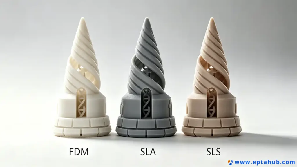
Not All Slicers Are Created Equal (FDM vs. SLA vs. SLS)
It is crucial to understand that slicing is not a universal language. The type of slicing you do depends entirely on the technology you are using.
If you are using a standard FDM (Fused Deposition Modeling) machine that melts a spool of plastic, your slicer is calculating toolpaths for a mechanical nozzle. It is obsessed with infill patterns, wall perimeters, and extrusion temperatures.
But what if you are using an entirely different technology?
Slicing for Resin (SLA / MSLA)
If we are using an SLA (Stereolithography) machine at EPTAHUB to print a high-resolution, transparent medical prototype, the slicing process changes completely.
An SLA machine does not use a nozzle. It uses a UV laser or an LCD screen to cure liquid resin. Therefore, an SLA slicer does not calculate infill patterns or nozzle temperatures. Instead, it calculates exposure times.
The slicer cuts the model into layers, and for each layer, it generates a black-and-white image (like a stencil). It then tells the machine exactly how many seconds to shine the UV light through that stencil to cure that specific layer of liquid resin.
Because resin is heavy and prints are usually pulled upside down out of a vat, SLA slicing is heavily focused on calculating weight distribution and generating microscopic, needle-like support structures to prevent the part from ripping off the build platform due to suction forces.
Slicing for Metal (DMLS / SLS)
When we move to industrial powder-bed fusion (where lasers melt nylon or titanium powder), the slicer is dealing with serious thermodynamics.
An SLS slicer doesn’t need to generate support structures to fight gravity, because the unfused powder in the bed naturally supports the part. Instead, the slicing algorithm is entirely focused on laser vectors and thermal management.
If the slicer tells the laser to scan back and forth too quickly in one area, it will create a massive heat pool that warps the metal. High-end metal slicers use complex algorithms to stagger the laser paths (sometimes called “island scanning”) to evenly distribute the thermal stress across the entire build plate.
Source Validation: The necessity of unique slicing strategies based on the additive process (extrusion vs. vat photopolymerization vs. powder bed fusion) is detailed extensively in the Wohlers Report, the industry-standard annual publication on additive manufacturing technology.
Conclusion: The Slicer is the Manufacturer
To summarize why slicing is critical: The 3D file represents the intent. The slicer represents the reality.
You can spend 100 hours designing the most perfectly optimized CAD model in the world. But if that model is handed to an inexperienced operator who uses the wrong slicing algorithm, chooses the wrong infill density, or fails to orient the part correctly to manage overhangs and layer adhesion, the physical part will fail.
When you send a STEP file to EPTAHUB, you are not just paying for access to our 500,000 USD machines. You are paying for the 12 years of engineering experience required to manipulate those slicer settings. You are paying for an engineer who knows exactly how to slice your specific geometry to maximize tensile strength, prevent thermal warping, and ensure the final physical part matches the digital dream.
You cannot 3D print without a slicer. And more importantly, you cannot manufacture a reliable product without an engineer who knows how to use one.