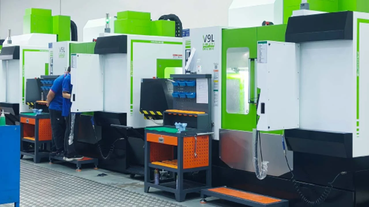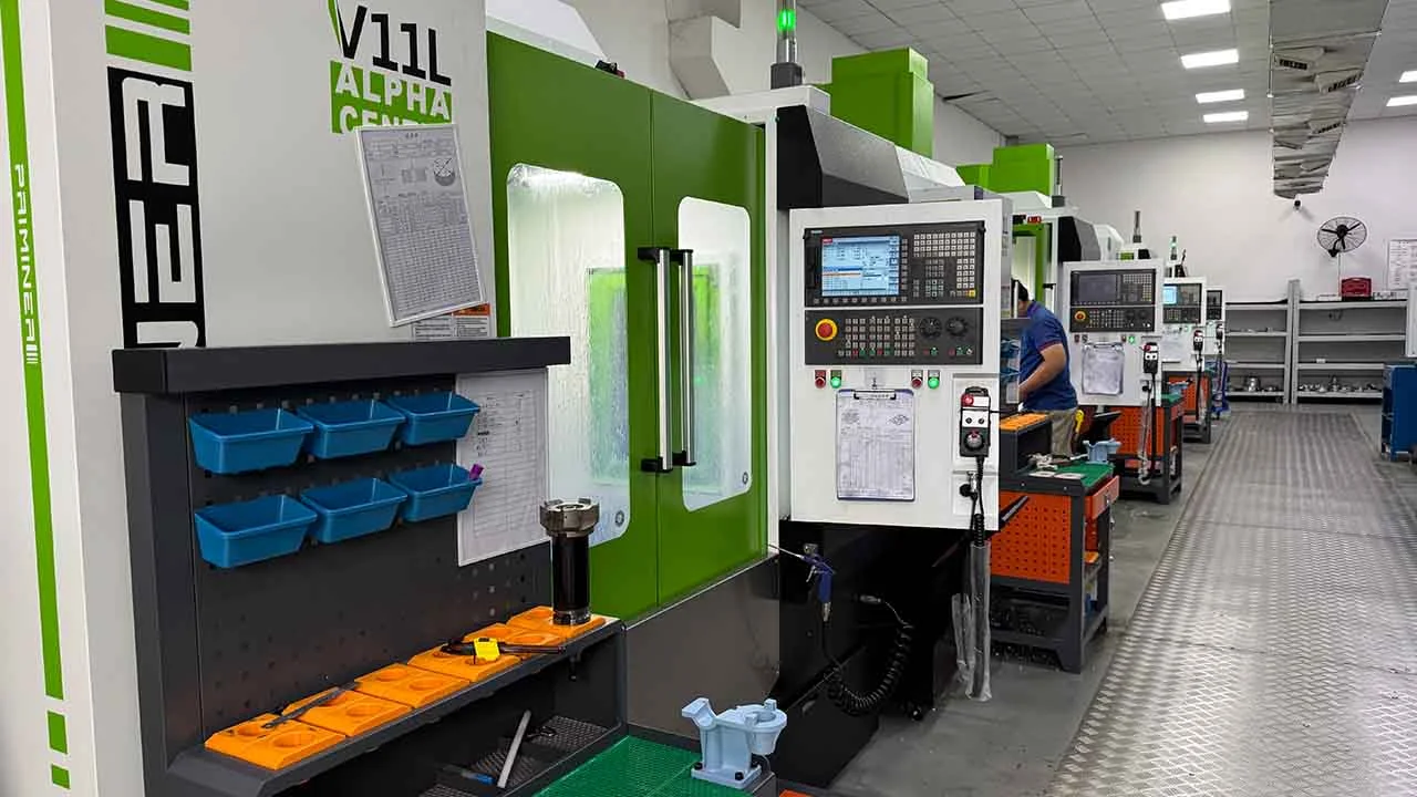
Every morning at EPTAHUB, my team opens up dozens of new project requests from product managers, hardware founders, and mechanical engineers. They all want the same thing: to turn their digital ideas into physical, high-quality parts using our industrial additive manufacturing fleet—machines that often cost upwards of 500,000 USD each.
Yet, roughly 40% of the time, the very first thing we have to do is hit “reply” and ask them to send a different file.
If you are new to the manufacturing side of product development, you have probably typed “What are the different files for 3D printing?” into a search engine. The problem is that the internet will usually feed you answers geared toward hobbyists. You will see articles about finding free stl files for 3d printing, links to consumer repositories like Thingiverse, and tutorials answering what file type for 3d printing ender 3 desktop machines.
If you are just having fun in your garage printing a plastic toy, grabbing a random file off the internet is perfectly fine. But if you are trying to launch a commercial product, prototype a precise medical enclosure, or manufacture a custom aluminum bracket, sending the wrong file type to a professional manufacturer is a massive roadblock. It leads to delayed quotes, failed prints, and thousands of USD in wasted time.
To a high-end 3D printer, your file is not just a picture; it is a strict set of mathematical instructions. If the math is wrong, or if the file format limits the data, the physical part will be wrong.
The Core Concept: Smart Models vs. Dumb Meshes
Before we argue about which file extension is the best, you have to understand the two fundamentally different ways computers think about 3D shapes. If you grasp this one concept, everything else about 3D printing files will make complete sense.
1. Solid Body Modeling (The “Smart” File)
When you design a part in professional CAD software like SolidWorks, Fusion360, or Inventor, the computer uses complex mathematics (called NURBS) to build the shape.
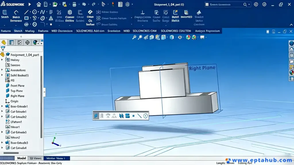
If you draw a cylinder, the software doesn’t draw a bunch of lines. It writes a mathematical equation defining the exact radius, the height, and the volumetric center. Because it is purely math, it is infinitely smooth and infinitely scalable. More importantly, it holds a “parametric history.” The computer knows why the shape looks the way it does. It is a smart file.
2. Polygonal Meshes (The “Dumb” File)
Now, let’s say you take that perfect mathematical cylinder and export it into a basic mesh format. The software immediately strips away all the math. It wraps the outside of your shape in a net made of hundreds of flat, 2D triangles.
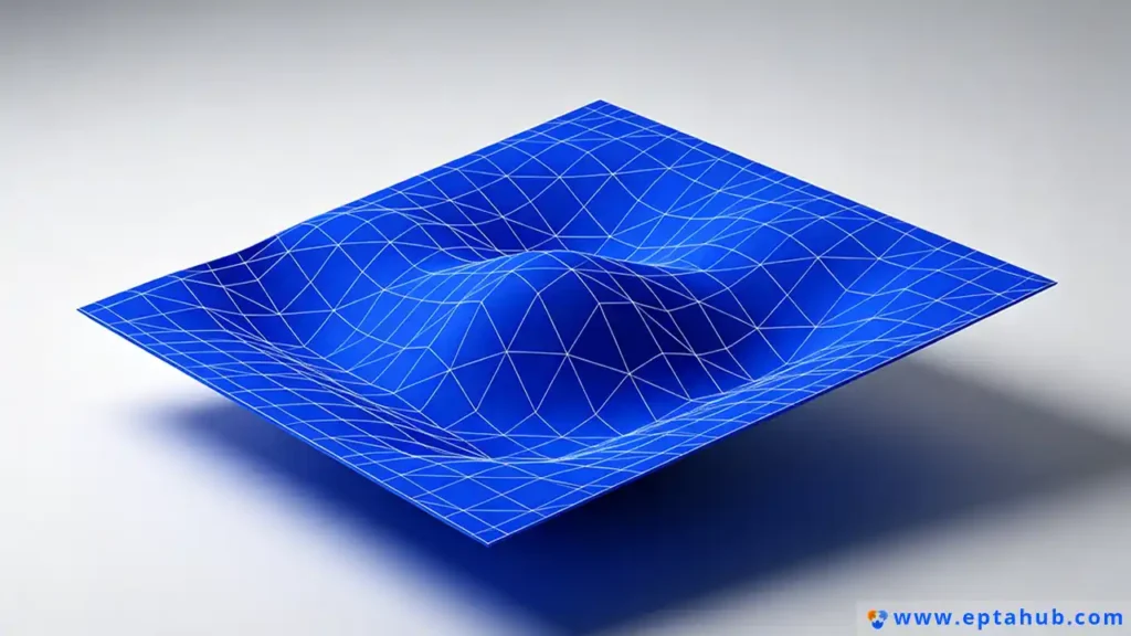
The computer no longer knows it is looking at a cylinder. It just sees a hollow shell made of triangles that happen to be arranged in a circular shape. The internal volume is gone, the curves are faked, and the mathematical history is erased. It is now a dumb file.
With that rule in mind, let’s look at the actual file formats you should (and should not) be uploading to EPTAHUB.
The Gold Standard: The STEP / STP File
If you ask any experienced manufacturing engineer, “What type of drawing is needed for 3d printing?”, they will all give you the exact same answer: Please, just send us the 3D STEP file.
The STEP file (Standard for the Exchange of Product model data, usually saved as .stp or .step) is the undisputed king of professional manufacturing.
Why is STP the Standard?
STEP is a universal, non-proprietary format that retains the “smart” solid-body geometry we just talked about. Whether your team designed the part in a 10,000 USD seat of premium engineering software or a basic student program, exporting it as a STEP file allows our engineers at EPTAHUB to open it natively without any translation errors or lost data.
Why EPTAHUB Demands STEP Files
When clients ask me, “Is STL or STP better for 3D printing?”, the answer is STP, and the reason is editability.
When you upload a file for a quote, it rarely goes straight to the printer. My team has to review it to make sure it will actually survive the printing process.
- If a snap-fit joint is too thin and will snap off during post-processing, we need to thicken it.
- If a hole is slightly too small for a standard screw, we need to open it up.
Because a STEP file is a smart, mathematical solid, my engineers can easily click on that hole and change the diameter from 3.0mm to 3.2mm in a matter of seconds. We can measure exact wall thicknesses and tweak the geometry to ensure your prototype is a success.
If you send us an STL file instead, we cannot do any of those things.
The Legacy Format: The STL File
If the STEP file is the hero of modern manufacturing, the STL file is the stubborn grandfather that refuses to retire.
Invented in the late 1980s, STL stands for Standard Tessellation Language. If you look at the search volume for the 3d printer file format stl, it is massive. It is the most common format in the world, and every single slicing program on earth accepts it.
But just because it is popular does not mean it is good.
The Fatal Flaw of STL Files
As we discussed, an STL file converts your beautiful CAD model into a dumb mesh of flat triangles. This creates two massive problems when you are trying to manufacture precise parts:
1. The Faceted Curve Problem (Resolution Issues)
Because an STL is made entirely of flat triangles, it cannot physically create a true curve. If you want a perfectly round peg to fit smoothly into a perfectly round hole, you are going to run into trouble.
When you figure out how to create stl files for 3d printing in your software, you are forced to choose an export “resolution.”
- If you set the resolution too low, the software uses fewer, larger triangles. Your perfectly round cylinder will print looking like a stop sign. It will be visibly faceted, and the parts will not fit together.
- If you set the resolution too high (trying to force the software to use millions of microscopic triangles to fake a smooth curve), the file size balloons to hundreds of megabytes. This creates massive, sluggish files that frequently crash slicing software.
2. The Zero-Editability Problem
When a client sends an STL file to EPTAHUB and casually asks us to “just move that mounting hole over by two millimeters,” they usually don’t realize they are asking for a minor miracle.
Because the STL is just a hollow shell of triangles, the computer doesn’t recognize the hole as a hole. To move it, we would have to manually grab hundreds of individual digital triangles and drag them across the screen without tearing a gap in the mesh. It is an incredibly frustrating process that wastes time. In most cases, we have to reject the file and ask the client to go back to their original software, make the change, and send a new file.
When is an STL Acceptable?
I am not saying you should never use an STL. If you are printing something purely aesthetic—like a topographical map, a contoured ergonomic handle, or an organic shape where exact mechanical tolerances do not matter—an STL is perfectly fine.
But if you are printing a mechanical enclosure or a custom fixture that requires exact, reliable dimensions, the STL format introduces an unnecessary layer of geometry approximation. Send the STEP file, and let the manufacturer’s high-end software handle the mesh conversion exactly when it is needed.
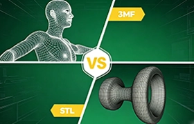
Which is Better, STL or OBJ?
If you spend any time looking at industrial design forums, you will inevitably see people arguing over “Which is better, STL or OBJ?”
To answer this, you have to look at where the OBJ file came from. The OBJ format wasn’t invented by mechanical engineers; it was developed by Wavefront Technologies for the 3D animation and video game industry.
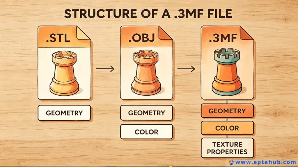
Like the STL, the OBJ is a polygonal mesh file. It breaks your model down into flat shapes. However, while an STL can only use triangles, an OBJ can use complex polygons (like quads and hexagons). But more importantly, the OBJ file carries a secret weapon: Data mapping.
When Color and Texture Matter
An STL file is completely blind to color. If you design a beautiful product casing in your software with a red logo and blue buttons, and you export it as an STL, the printer just sees a single, grey blob.
An OBJ file, however, can carry an attached .MTL (Material Template Library) file. This extra file tells the 3D printer exactly what color every single polygon should be.
If you come to EPTAHUB and want to use our PolyJet technology (a highly advanced printing process that can print full-color, photorealistic prototypes), an STL is useless. We need the OBJ file to tell our machine where to inject the red resin and where to inject the transparent resin.
So, which is better?
- If you are printing a purely structural metal bracket via DMLS, they are identical (and you should really be using a STEP file anyway).
- If you are printing a full-color architectural model or a consumer product mockup that needs to look exactly like the final product for a marketing photoshoot, the OBJ is vastly superior.
The Modern Replacement: What is the 3MF File?
For decades, the 3D printing industry has complained about the limitations of STL files. They are too big, they don’t carry color data, and they are prone to mathematical errors (which we will cover next).

A few years ago, a consortium of major tech companies (including Microsoft, HP, and Autodesk) got together and decided to finally kill the STL. They created the 3MF (3D Manufacturing Format).
If you are looking at modern 3d printing software, you will notice that almost all of them are pushing you to save your projects as .3mf files.
Why the 3MF is the Future of the Industry
The 3MF file was built specifically for the realities of modern additive manufacturing.
- It is an All-in-One Package: Unlike OBJ, which requires a separate
.MTLfile for color, a 3MF file compresses the geometry, the color data, the material properties, and even the printer settings (like support structures and infill density) into one single, lightweight zip archive. - It Prevents Errors: 3MF files are inherently built to avoid the “non-manifold” errors that constantly plague STL files.
- Smaller File Sizes: A highly detailed mesh that takes up 150 Megabytes as an STL might only take up 30 Megabytes as a 3MF, making it vastly easier to email to a manufacturer or upload to a quoting portal.
At EPTAHUB, if a client insists on sending a mesh file instead of a solid CAD model, we highly encourage them to use 3MF over STL. It simply creates fewer headaches for everyone involved.
Are All 3D Print Files the Same?
The short answer is no. But the longer, more painful answer is that even if two files have the exact same .stl extension, one might print perfectly, and the other might crash a 100,000 USD machine.
This brings us to the most common reason we have to reject client files: Non-Manifold Geometry.
The “Water-Tight” Rule
To understand how a 3D printer reads a file, you have to think about water.
A 3D printer must be able to calculate exactly what is “inside” the part (where it needs to melt plastic or laser metal) and what is “outside” the part (where it needs to leave empty space).
For the printer software to make this calculation, the 3D mesh must be “manifold”—which is an engineering term for “completely water-tight.” If you were to fill your digital 3D model with virtual water, not a single drop could leak out.
How Bad Files Are Born
When people download free stl files for 3d printing from random internet forums, or when novice designers try to stitch different shapes together in basic CAD software, they often create non-manifold errors without realizing it:
- Holes in the Mesh: If even one tiny triangle is missing from the surface of your STL file, the mesh is no longer water-tight. When the slicing software reaches that missing triangle, it gets confused. It doesn’t know where the inside of the part stops and the outside begins. It will often simply refuse to print, or worse, it will print a solid block of plastic instead of a hollow cup.
- Intersecting Geometry: If you take a digital cylinder and shove it halfway through a digital cube, they look fine on your computer screen. But to a 3D printer, those overlapping internal walls create a mathematical paradox. The software cannot calculate the toolpath.
- Inverted Normals: Every triangle in a mesh has an “outside” face and an “inside” face. Sometimes, during export, a few triangles get flipped backward. The software reads this as a physical impossibility and crashes.
When you send a STEP file to EPTAHUB, these errors literally cannot exist, because a STEP file is a mathematical solid. But if you send an STL, our engineers have to run it through specialized mesh-repair software (like Magics or Netfabb) to “heal” these microscopic holes and flipped triangles before we can even quote the job.
2D Prints vs 3D Files: What Type of Drawing is Needed for 3D Printing?
A very common situation we run into at EPTAHUB is an experienced procurement manager or older mechanical engineer sending us a traditional 2D PDF blueprint (a mechanical drawing) and asking us to 3D print the part.
When people ask, “What type of drawing is needed for 3D printing?”, they are often confusing traditional machining with additive manufacturing.
Why 2D Drawings Cannot Be Printed
If you want us to CNC mill a block of aluminum, a 2D PDF drawing is highly useful. A skilled machinist can look at the top, side, and front views on the paper, read the dimensions, and manually program the toolpaths into the machine controller.
But a 3D printer is not a machinist. A 3D printer only understands 3D space. You cannot feed a 2D PDF into slicing software. The machine has absolutely zero ability to “read” a blueprint and extrude plastic based on text annotations.
If you only have a 2D drawing, our engineering team has to sit down at a computer and manually rebuild the entire part from scratch in 3D CAD software before we can print it. This reverse-engineering process adds significant time and USD to your final invoice.
Why You Still Need to Send the 2D PDF (The Tolerance Trap)
So, should you just throw away your 2D drawings? Absolutely not.
While the 3D file (the STEP or STL) gives the machine the physical shape, the 2D drawing gives the human engineer the intent.
A 3D file does not contain tolerances. If your STEP file shows a hole that is exactly 10.00mm wide, the 3D printer will attempt to print it exactly 10.00mm wide. But in reality, plastic shrinks when it cools. Metal warps when it is laser-sintered. That 10.00mm hole might actually finish at 9.92mm.
If you just send the 3D file, we don’t know if that hole is just for routing a loose wire, or if you need to press-fit a highly precise stainless steel bearing into it.
If you send the 3D file along with a 2D PDF drawing that explicitly calls out a strict +/- 0.05mm tolerance on that specific hole, our engineers at EPTAHUB will see it. We will intentionally scale the 3D file up slightly before printing, or we will plan to physically run a reaming tool through the hole after printing to ensure the bearing fits perfectly.
The rule is simple: The 3D file makes the part. The 2D drawing makes the part work.
The EPTAHUB File Submission Checklist
If you are reading this, you are likely trying to get a project off the ground. You want an accurate quote, and you want your parts to arrive on time and function correctly.
To bypass the typical headaches and avoid having your files rejected by manufacturing engineers, follow this exact checklist before you hit the “submit” button:
1. Ditch the STL (Unless it is Purely Aesthetic)
If your part needs to fit into another part, hold a tight tolerance, or survive a structural load, do not export an STL file. Go into your CAD software and export a .STEP (or .STP) file. This single habit will solve 90% of the manufacturing delays we see.
2. Use 3MF for PolyJet or Multi-Color Prints
If you are designing a complex, multi-material prototype (like a rigid case with a soft, rubberized over-mold grip), export the assembly as a .3mf file. This ensures all the color and material zone data translates perfectly to our high-end printers.
3. Zip Large Assemblies
If you are sending an assembly with 15 different components, do not upload 15 individual STL files named “Part 1, Part 2, etc.” Export the entire assembly as a single STEP file, or zip them into one folder. This ensures all the parts maintain their correct X, Y, Z coordinates relative to each other, allowing us to see how the whole machine fits together.
4. Include the PDF for Critical Tolerances
If a specific surface needs to be perfectly flat, or a hole needs a tapped thread (like an M4 x 0.7 thread), include a 2D PDF drawing calling out those specific features. Additive manufacturing is amazing, but it is not magic; we still need to know your engineering intent.
5. Check for Manifold Errors (If Forced to Use STL)
If you absolutely must use an STL file, run it through a free mesh-checker (like Microsoft’s 3D Builder or Meshmixer) before you send it out. If the software flags “non-manifold edges” or “open boundaries,” you need to fix your CAD model. If you don’t fix it, the manufacturer’s software will either crash or attempt to auto-repair it, which often drastically alters the shape of your part.
Conclusion: Stop Designing for the Screen
The biggest shift you have to make when transitioning from consumer-level 3D printing to industrial manufacturing is realizing that the digital file is just a set of instructions.
It does not matter how beautiful the rendering looks on your computer monitor. If the geometry is fundamentally flawed, if the mesh is broken, or if the file format lacks parametric data, the final physical part will fail.
By standardizing around the STEP file and understanding the limitations of legacy formats like STL, you allow manufacturers like EPTAHUB to stop fixing broken meshes and start focusing on what we do best: optimizing your designs, selecting the right industrial materials, and getting high-quality parts into your hands as fast as possible.