Hello, I’m a senior engineer at Eptahub. In my dozen years on the shop floor and in design review meetings, I’ve seen that some manufacturing processes are universally understood, while others live in a gray area of myth and misconception. Brazing is squarely in that second category.
Many engineers see it as a kind of “super-solder” or a “weaker weld.” This misunderstanding can lead to missed opportunities for creating lighter, stronger, and more cost-effective assemblies. On the flip side, a poorly specified braze joint can be the root cause of catastrophic field failures.
This guide is my attempt to pull brazing out of the shadows and put it into your toolkit as a reliable, predictable, and incredibly versatile joining technology. We’re not just going to define it. We’re going to dismantle it, look at every component and every step, and give you the practical knowledge you need to design for it and, just as importantly, to source it effectively.
Here’s what we’ll cover, from an engineer’s perspective:
- The Physics of Brazing: We’ll go beyond the dictionary to understand capillary action and why the base metals don’t melt.
- The Anatomy of the Joint: A deep dive into the three key players: base metals, filler metals, and flux.
- A Step-by-Step Walkthrough: The six critical stages of a successful brazing operation, and where things most often go wrong.
- Brazing vs. Welding vs. Soldering: A clear, practical comparison to help you make the right call every time.
- A Tour of Industrial Brazing Methods: From a skilled hand with a torch to the high-tech precision of a vacuum furnace.
- Designing for Success: How to create joints that are strong, reliable, and manufacturable.
- Sourcing with Confidence: A detailed checklist for creating an RFQ that gets you accurate quotes and eliminates ambiguity.
Let’s begin by establishing a rock-solid foundation.
The Core Principle: How Brazing Actually Works
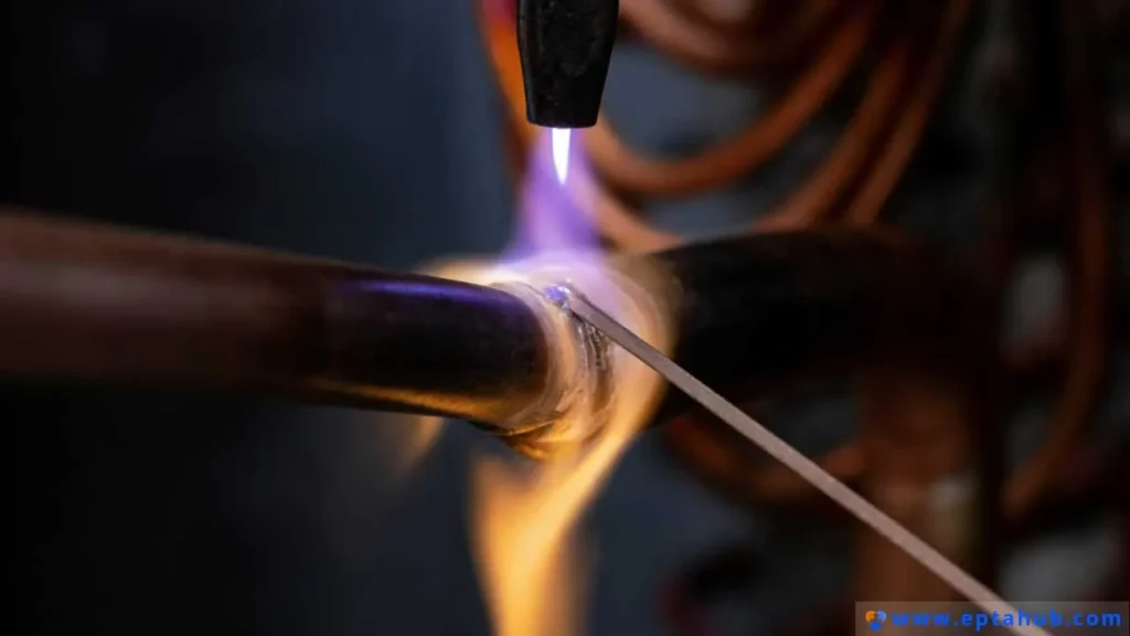
At its heart, brazing is a metal-joining process where a filler metal is heated above its melting point and distributed between two or more close-fitting parts by capillary action. This is the single most important concept to grasp.
Let’s break down the three non-negotiable conditions set by the American Welding Society (AWS):
- The Base Metals Are Heated, But Never Melted. This is the fundamental difference between brazing and welding. In welding, you create a fusion by melting the edges of the base materials, creating a single, continuous piece. In brazing, the integrity of the base metals is maintained. You are essentially creating a high-strength, metallurgical “glue” that bonds the parent materials together. This lower temperature input is the source of many of brazing’s key advantages, particularly low distortion.
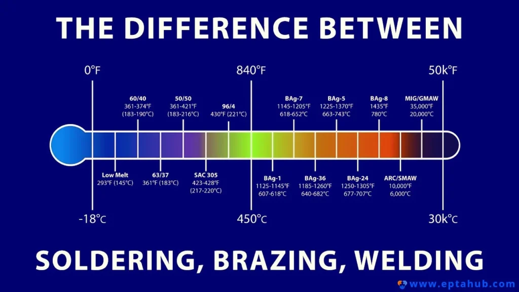
- The Filler Metal Melts Above 450°C (840°F). This temperature threshold is the arbitrary but universally accepted line that separates brazing from its lower-temperature cousin, soldering. The alloys used in brazing are serious engineering materials—silver, copper, nickel, and even gold-based alloys—that create joints with very high strength.
- The Filler Metal Flows via Capillary Action. This is the magic. Capillary action is the tendency of a liquid to be drawn into a small space, even against the force of gravity. It’s the same phenomenon that pulls water up a paper towel. For this to happen in brazing, two things are essential: the surfaces must be exceptionally clean, and the gap between the parts (the “joint clearance”) must be precisely controlled. The molten filler “wets” the hot base metal surfaces and the power of surface tension pulls it deep into the joint, ensuring a complete and uniform bond.
When these three conditions are met, you create a brazed joint that is not just sealed, but structurally sound. In many cases, a properly designed braze joint can be stronger than the base metals themselves.
The Anatomy of a Braze Joint: The Three Key Elements
Every braze joint is a system composed of three elements. A failure in any one of them will result in a failure of the entire system.
The Base Metals
These are the components you are joining. Brazing’s greatest strength is its ability to join a wide variety of dissimilar metals, something that is often difficult or impossible with welding. Common base metals we see at Eptahub include:
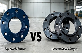
- Steels: Carbon steel, alloy steel (like 4140), and stainless steels (304, 316) are all readily brazed.
- Copper and Copper Alloys: This includes pure copper, brasses, and bronzes. They are among the easiest materials to braze.
- Nickel Alloys: Materials like Monel and Inconel are often brazed for high-temperature or corrosive service applications.
- Carbides: A classic brazing application is joining a tungsten carbide tip to a steel tool shank for cutting tools or wear parts.
The key is knowing the properties of your base metals, as the brazing temperature can affect their heat treatment or work-hardened state.
The Filler Metals
This is the alloy that melts and flows into the joint. It’s not just a single material; filler metals come in dozens of standard formulations, each with a unique combination of melting temperature, strength, ductility, corrosion resistance, and cost. They are typically specified by an AWS classification, such as “BAg-7” or “BCuP-5”.
Here are the main families:
- Silver-based Fillers (BAg series): These are the most versatile and widely used alloys. They have relatively low melting points, excellent flow characteristics, and create strong, ductile joints on most metals (steels, coppers, nickel). The amount of silver is a major cost driver.
- Copper-based Fillers (BCu series): This group includes pure copper and copper-phosphorus alloys.
- Pure Copper (BCu-1): Primarily used for furnace brazing steel in a reducing atmosphere. It’s very cost-effective.
- Copper-Phosphorus (BCuP series): The workhorse for joining copper to copper in the HVAC and plumbing industries. The phosphorus acts as a fluxing agent, so no separate flux is needed on copper-to-copper joints. Crucial Warning: These fillers should never be used on ferrous (steel) or nickel alloys, as they can form brittle phosphides and cause joint failure.
- Aluminum-silicon Fillers (BAlSi series): Used specifically for brazing aluminum alloys. They have a very narrow melting range, just below the melting point of the aluminum base metals, requiring extremely precise temperature control.
- Nickel-based Fillers (BNi series): Used for high-temperature and high-strength applications, such as in aerospace engines or for joining stainless steels that will see corrosive service. They have excellent strength retention at elevated temperatures.
- Gold-based Fillers (BAu series): These are specialty, high-cost fillers used in aerospace and medical applications where supreme reliability, oxidation resistance, and ductility are required.
The Flux
If the surfaces aren’t perfectly clean, the filler metal won’t wet them, and the joint will fail. Flux is the chemical insurance policy for a good braze. It’s a compound applied to the joint before heating that performs three critical jobs:
- It dissolves surface oxides. Even a freshly cleaned part has a thin, invisible layer of oxide. Flux chemically removes this layer as the part heats up.
- It prevents re-oxidation. As the part is heated in air, it will try to form new, thicker oxides. A blanket of flux shields the joint area from the atmosphere.
- It promotes wetting. By providing a clean, oxide-free surface, flux helps the molten filler metal spread out and flow smoothly into the joint.
Fluxes come in paste, powder, and liquid forms and must be matched to the base metals, filler metal, and brazing temperature range. For example, a flux designed for silver brazing steel won’t work for aluminum brazing. After brazing, it is absolutely essential to remove all residual flux, as most types are corrosive and can attack the joint over time.
The only time you can typically skip flux is during furnace brazing in a controlled atmosphere (like a vacuum or pure hydrogen), where the atmosphere itself prevents oxidation.
The Step-by-Step Brazing Process: A Walkthrough of the Six Stages
A perfect braze joint is the result of a disciplined, sequential process. As an engineer sourcing a brazed assembly, understanding these steps helps you appreciate where the cost and quality are built in.
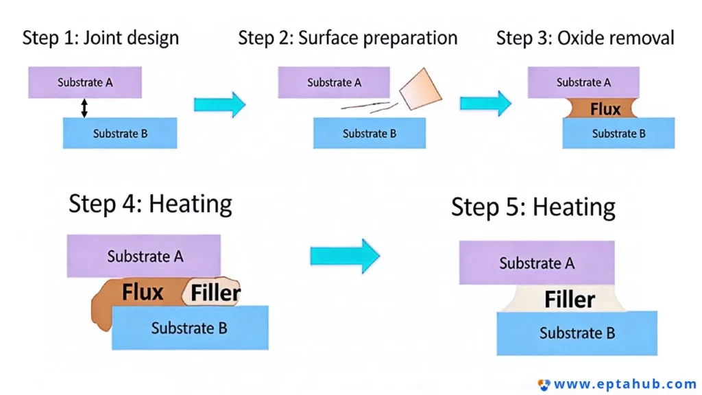
Stage 1: Design a Proper Joint
Success or failure begins on the CAD screen. Because brazing relies on capillary action, the gap between the parts—the joint clearance—is the most critical design parameter.
- The Golden Rule of Clearance: For most common filler metals, the ideal joint clearance at brazing temperature is 0.025 mm to 0.127 mm (0.001″ to 0.005″).
- Why this range?
- Too tight (<0.025 mm): The molten filler metal struggles to penetrate the joint, leading to voids.
- Too loose (>0.127 mm): The force of capillary action is lost. The filler won’t be able to fill the gap completely, and the resulting joint will have low strength due to a thick, cast-like structure.
- Thermal Expansion is Key: Remember, that clearance is specified at brazing temperature. If you are joining two different materials (e.g., a steel pin into a copper block), you must account for their different coefficients of thermal expansion. The copper will expand more than the steel when heated. Your “cold” clearance at room temperature must be calculated to achieve the target “hot” clearance.
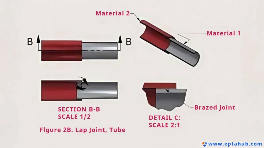
- Joint Types: The most common type is a lap joint, where one part overlaps the other. This provides a large surface area for the braze, maximizing strength. A rule of thumb for a joint as strong as the weaker member is an overlap length of at least three times the thickness of the thinnest member. A butt joint (end-to-end) is simpler but provides a much smaller bonding area and is generally weaker.
Stage 2: Clean the Surfaces Meticulously
I’ll say it again: most brazing failures are traceable to poor cleaning. The surfaces to be joined must be completely free of oil, grease, cutting fluid, dirt, scale, and oxides. The filler metal will not bond to a contaminated surface.
- Chemical Cleaning: This is the first step, designed to remove organic contaminants. Solvents, vapor degreasing, or alkaline cleaning solutions are used to get rid of any oils or grease.
- Mechanical Cleaning: This step is to remove oxides and scale. Sanding with abrasive cloth, wire brushing (with a stainless steel brush, never carbon steel), or grit blasting are common methods. This creates a fresh, active surface ready for the flux and filler.
Stage 3: Apply Flux and Assemble
Once clean, flux should be applied to the joint area as soon as possible. Apply a thin, even layer to both components. The flux protects the parts as they are assembled and heated.
The components are then assembled. The design should ideally be self-fixturing, using pins, shoulders, or press-fits to hold the parts in the correct alignment and with the correct clearance. If external fixtures are needed, they should be designed to minimize contact with the assembly and be made from a material (like stainless steel or a ceramic) that won’t get brazed to the parts.
The filler metal is often pre-placed at this stage in the form of a wire ring, shim, or paste. This ensures the right amount of filler is available and allows for a more repeatable process, especially in furnace or induction brazing.
Case Study: The Leaking HVAC Coil Assembly
- The Scenario: A manufacturer of commercial air conditioning units was experiencing a high failure rate during the final pressure test of their evaporator coils. The coils consisted of hundreds of copper tubes brazed into two large steel tube sheets. About one in every five assemblies had a slow leak.
- The Initial Assumption: The operators on the manual torch brazing line were being blamed for poor technique. Management was considering a massive investment in automated brazing cells.
- Our Investigation: We were asked to audit the process before they made the capital expenditure. We walked the line from start to finish. The operators were highly skilled, the joint design was good, and the flux application was correct. The problem wasn’t in the final heating step. The issue was earlier. The copper tubes, arriving from a supplier, were bright and clean. But the steel tube sheets were laser-cut and had a thin, tough, almost invisible oxide layer around each hole. The pre-braze cleaning process consisted of a single solvent wipe-down.
- The Root Cause: The solvent was removing any oil, but it was doing absolutely nothing to the oxide layer on the steel. During heating, the flux was being exhausted just trying to break down this heavy oxide, leaving nothing to protect the joint when the filler metal was introduced. The filler couldn’t properly wet the steel, resulting in tiny, intermittent voids—the source of the leaks.
- The Simple Solution: We implemented a new step immediately after the solvent wipe. An operator used a simple rotary abrasive brush to quickly scuff the inside of each hole on the steel tube sheets. This took less than 10 seconds per hole and provided a fresh, oxide-free surface.
- The Result: The leak rate fell from 20% to under 0.5% within a week. The company saved millions by avoiding unnecessary automation and instead fixing the most fundamental step in the process: proper cleaning. This case is a perfect illustration of how a deep understanding of the process can solve complex problems with simple, targeted solutions.
Stage 4: Heat the Assembly Uniformly
Now it’s time to bring the heat. The goal is to heat the assembly broadly and uniformly to the brazing temperature. The specific method—torch, furnace, induction—will determine how this is done, but the principle is the same.
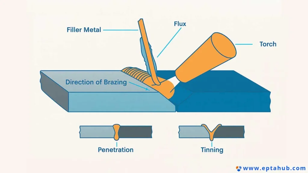
When using a torch, the flame should be aimed at the thicker of the two components to heat the entire joint region evenly. You heat the base metals, and the base metals melt the filler metal. Never point the flame directly at the filler metal itself. A common mistake is to melt the filler onto a joint that isn’t hot enough for it to flow, resulting in a poor bond.
Stage 5: Apply Filler Metal (If Not Pre-placed)
Once the assembly reaches the correct temperature (often indicated by the flux becoming clear and watery), the filler metal is introduced to the edge of the joint. If the temperature and conditions are right, capillary action will instantly pull the molten filler through the entire joint. You’ll often see a bright, shiny fillet appear on the other side, which is a good visual indicator of a successful braze.
Stage 6: Cool, Clean, and Inspect
After the filler has flowed, the assembly must be cooled. For many materials, air cooling is sufficient. Quenching in water can be used for some alloys, but it risks thermal shock and cracking on others.
Once the part is cool, the final and critical step is to remove all residual flux. As mentioned, most fluxes are corrosive. Soaking in hot water, followed by brushing, is the most common method. The final part is then inspected visually for a complete fillet around the joint, and if required by the specification, subjected to pressure testing, leak testing, or non-destructive examination like X-ray.
The Great Debate: Brazing vs. Welding vs. Soldering
One of the most frequent conversations I have with designers is helping them decide between these three core joining processes. Making the right choice early in the design cycle can save an immense amount of time, money, and heartache down the line. They all join metal, but they live in different universes in terms of temperature, strength, and impact on the base materials.
Let’s put them side-by-side in a detailed breakdown.
Table 1: Brazing vs. Welding vs. Soldering – A Technical Comparison for Engineers
| Feature | Soldering | Brazing | Welding |
|---|---|---|---|
| Defining Temperature | Filler metal melts below 450°C (840°F). | Filler metal melts above 450°C (840°F). | Heats to the melting point of the base metals. |
| Effect on Base Metals | Base metals are not melted. Thermal effect is minimal. | Base metals are not melted. The thermal cycle is significant and can affect heat treatments, but avoids the stresses of melting and solidification. | Base metals are melted and fused together. This creates a continuous structure but induces significant thermal stress, distortion, and a large Heat-Affected Zone (HAZ). |
| Resulting Joint Strength | Low. Typically ranges from 15 to 150 MPa (2,000 to 22,000 psi). Relies on weak, low-temperature alloys. | High. Typically ranges from 275 to 825 MPa (40,000 to 120,000 psi). A well-designed joint is often stronger than the parent metals. | Highest. The strength of the joint is typically equivalent to or greater than that of the base metals. |
| Capillary Action | Yes, used to fill the joint. | Yes, this is the primary mechanism for distributing the filler metal throughout the joint. | No. Filler metal (if used) is deposited directly into the joint. The process relies on fusion, not capillary flow. |
| Joining Dissimilar Metals | Good. Excellent for joining metals with widely different melting points, like copper to brass. | Excellent. This is a primary advantage of brazing. It’s the go-to process for joining steel to copper, carbide to steel, or aluminum to copper. | Difficult and often impossible. Metallurgical incompatibility can lead to brittle intermetallic compounds at the fusion line, causing joint failure. Requires specialized techniques and buttering layers. |
| Thermal Distortion & Stress | Very Low. The minimal heat input makes it ideal for delicate and heat-sensitive components. | Low. The heat is applied more uniformly and at a lower temperature than welding. Furnace brazing, in particular, minimizes distortion by heating the entire assembly at a controlled rate. | High. The intense, localized heat from an arc or flame creates steep thermal gradients, leading to significant warping, distortion, and high residual stresses that may require post-weld heat treatment. |
| Typical Applications | Electronics (PCBs), low-pressure plumbing, stained glass, jewelry. | Aerospace fuel lines, HVAC assemblies, carbide cutting tools, heat exchangers, bicycle frames, musical instruments. | Structural steel frames, pressure vessels, automotive chassis, shipbuilding, pipelines, heavy equipment fabrication. |
The Engineer’s Decision-Making Summary:
- When to choose Welding: Choose welding when you need the absolute maximum joint strength, are joining thick sections (over a few millimeters), and are working with similar or identical metals. If the part is a primary structural component on a bridge or a pressure vessel, welding is the answer. Be prepared to manage significant thermal distortion and residual stress.
- When to choose Brazing: Choose brazing when you need a strong, leak-proof joint and one or more of these conditions apply:
- You are joining dissimilar metals.
- You need to minimize thermal distortion on a precision assembly.
- You are joining thin-walled sections that would be destroyed by welding.
- The assembly geometry is complex or has multiple joints that can be made simultaneously in a furnace.
- The part requires a clean, neat joint with no post-processing.
- When to choose Soldering: Choose soldering for low-stress, low-temperature applications. If you are joining components on a printed circuit board or sealing a non-structural seam, soldering provides a sufficient bond with minimal heat input.
Choosing Your Weapon: A Tour of Industrial Brazing Methods
The way an assembly is heated is a critical process variable. The choice of heating method affects everything from the quality of the joint to the cost and speed of production.
Torch Brazing
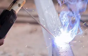
This is the most common manual method. An operator uses a handheld torch, typically fueled by oxy-acetylene or a natural gas/air mixture, to heat the parts and flow the filler metal.
- Pros: Highly versatile, low capital investment, portable, and excellent for repair work or one-off prototypes. A skilled operator can braze complex geometries that are difficult to fixture for other methods.
- Cons: Extremely dependent on operator skill. Overheating is a common risk, which can damage the base metals or boil away elements in the filler alloy. Consistency from part to part can be a challenge. It’s generally not suitable for high-volume production.
- Best For: Low-volume assemblies, large or awkwardly shaped parts, field repairs, and prototyping.
Furnace Brazing
In this method, the entire assembly, with filler metal pre-placed, is loaded into a furnace. The furnace is then filled with a controlled atmosphere and heated in a precise, pre-programmed cycle.
- The Atmosphere is Key: The atmosphere prevents oxidation, eliminating the need for flux. Common atmospheres include:
- Vacuum: Provides the highest purity environment, ideal for reactive metals like titanium or for medical and aerospace components where cleanliness is paramount.
- Hydrogen/Reducing Atmosphere: An active atmosphere that chemically “reduces” (cleans) surface oxides from metals like steel, copper, and nickel. Excellent for high-volume production of clean parts.
- Pros: Produces exceptionally clean, high-quality, and consistent joints. Uniform heating minimizes thermal distortion. Allows for hundreds or thousands of parts—or a single part with hundreds of joints—to be brazed in a single cycle. Highly repeatable and controllable.
- Cons: High capital equipment cost. Parts must be able to fit within the furnace’s hot zone. Not suitable for one-off jobs due to the long cycle times.
- Best For: High-volume production, complex multi-joint assemblies (like heat exchangers), medical and aerospace components, and parts requiring extreme cleanliness.
Induction Brazing
Induction brazing uses a high-frequency alternating current passed through a custom-designed copper coil. This creates a powerful electromagnetic field that rapidly heats the conductive assembly placed within it.
- Pros: Extremely fast and energy-efficient. The heating is localized, precise, and highly repeatable, making it perfect for automation. Creates a very small heat-affected zone.
- Cons: The initial cost of the equipment can be high. The induction coils must be custom-designed for each specific part geometry, which adds to the tooling cost.
- Best For: High-volume, repeatable production of small- to medium-sized parts with simple joint geometries, such as attaching fittings to tubes or brazing carbide tips onto tool bodies.
A Note on Braze Welding vs. Brazing
This term often causes confusion. While a standard braze joint uses capillary action to fill a very narrow gap, braze welding is a different beast. It’s a manual process, similar to torch welding, but using a brass or bronze filler rod at a temperature below the melting point of the base metal.
- Key Difference: Braze welding does not use capillary action. It’s used to fill gaps, V-grooves, or create large fillets, much like TIG or oxy-acetylene welding. The operator “tins” the surface and then builds up layers of filler metal.
- Application: It’s most commonly used for repairing cast iron parts, as the lower temperature input avoids the cracking problems associated with welding cast iron. If your drawing has a V-groove and calls for a brass filler, it’s likely a braze welding operation, not a capillary braze.
Sourcing with Confidence: How to Build a Bulletproof RFQ
As the engineer receiving your RFQ, I can tell you this: the quality of your technical package directly determines the quality of your quote and, ultimately, the quality of your parts. Ambiguity is the enemy of good manufacturing. A vague RFQ forces us to make assumptions, which means we either pad the quote to cover unknown risks or we have to delay the quote while we send you a list of questions.
Case Study 2: The Ambiguous Sensor Housing RFQ
- The RFQ: We received a request for 5,000 units of a sensor assembly. The drawing showed a 316 stainless steel housing and a Kovar pin. The note simply said: “Braze pin to housing. Must be hermetically sealed to 1×10⁻⁸ cc/sec He.”
- The Red Flags: This is a classic “dangerously incomplete” specification.
- No Filler Metal Specified: For a hermetic seal on Kovar, you might use a high-reliability gold-tin (AuSn) alloy or a more standard silver-copper eutectic (BAg-8). The cost difference is enormous—we’re talking a potential 10x difference in filler material cost alone.
- No Process Constraints: Should this be furnace brazed in a vacuum for ultimate cleanliness? Or is a more economical hydrogen furnace acceptable? Does the part require post-braze plating that might be incompatible with certain filler metals?
- No Joint Clearance: The individual component drawings didn’t specify the pre-braze clearance between the pin and housing. We couldn’t know if the design would even allow for proper capillary flow.
- The Outcome: We couldn’t quote it. We had to go back to the customer’s engineer with a detailed list of questions. The quoting process was delayed by three days. It turned out their design assumed a low-cost silver filler, but their hermeticity requirement was so stringent that a gold-based filler would have been more reliable. This led to a scramble of testing and re-qualification on their end. A detailed initial spec would have identified this mismatch between cost and performance requirements from the very beginning.
To avoid this, build your RFQ package with the following information.
Table 2: The Engineer’s RFQ Checklist for Brazed Assemblies
| Category | Information to Provide | Why It’s Critical for Your Supplier |
|---|---|---|
| 1. Complete Drawings & Models | • 2D Assembly Drawing (PDF): Showing the final assembly. • 2D Component Drawings (PDF): For each individual part before brazing. • 3D Model (STEP): Of the assembly. |
The assembly drawing shows us the “what.” The component drawings are crucial because they must show the pre-braze dimensions and the critical joint clearance we need to achieve. |
| 2. Precise Material Specs | • Specify the exact material and standard for each component (e.g., “304 Stainless Steel, ASTM A240” and “Oxygen-Free Copper, UNS C10100”). Avoid vague terms. | This is non-negotiable. It dictates filler metal choice, flux, thermal expansion calculations, and the brazing atmosphere. “Steel” is not a material specification. |
| 3. Braze Filler Metal Callout | • Specify the filler metal using a standard designation (e.g., “AWS BAg-7”). • Specify its form (e.g., “0.8mm wire ring” or “paste”). |
This is the single biggest driver of joint properties and cost. If you’re unsure, provide performance requirements (see next point) and let us recommend an alloy. |
| 4. Critical Performance Specs | • Strength: “Joint must withstand X shear load.” • Pressure/Leak Tightness: “Must be leak-free at X pressure” or “Hermetic to X leak rate.” • Service Environment: “Operating temp of X°C,” “Exposure to saltwater.” |
This is the “why” behind your design. It tells us what the joint needs to do. This information allows us to validate your filler choice or suggest a better, more cost-effective alternative. |
| 5. Joint Location & Fillet | • Clearly indicate on the drawing which joints are to be brazed. • Note any requirements for the final fillet size (e.g., “Smooth, continuous fillet required”). |
Don’t make us guess where the braze goes. Fillet requirements can affect the amount of filler metal used and the post-braze cleaning process. |
| 6. Post-Braze Requirements | • Cleaning: “All flux residue must be removed.” • Post-Processing: Call out any subsequent operations like machining, plating, or painting. • Inspection: Specify any required NDT like pressure testing, dye penetrant, or X-ray. |
These steps have significant cost and lead time implications. If a part needs to be nickel-plated after brazing, we need to choose a filler metal compatible with the plating chemistry. |
| 7. Documentation & Quality | • Specify if you need a Certificate of Conformance (CoC), material certifications for the base and filler metals, or inspection reports. | At Eptahub, we can provide full documentation, but it’s an administrative step that needs to be planned for. Only request what your quality system truly requires. |
Frequently Asked Questions (FAQ)
Q: What is brazing in HVAC?
A: In HVAC systems, brazing is the standard method for joining copper tubing for refrigerant lines. The filler metal used is almost always a copper-phosphorus alloy (like BCuP-5). The phosphorus acts as a fluxing agent on copper, so for copper-to-copper joints, no external flux is needed. This makes the process clean and efficient for field technicians. These joints are strong and, critically, leak-proof to contain high-pressure refrigerants.
Q: What metals cannot be brazed?
A: While brazing is versatile, some metals are problematic. Magnesium and its alloys are generally not brazed due to their high reactivity. Metals with melting points below the brazing temperature range, like lead, tin, or zinc, obviously cannot be brazed. Aluminum can be brazed, but it requires special fluxes and very tight temperature control, making it a specialized process.
Q: Does brazing weaken the base metal?
A: It can, and this is a critical design consideration. The brazing temperature is high enough to anneal (soften) any cold-worked or heat-treated base metals. For example, if you braze a fitting onto a piece of hardened 4140 steel, the area around the joint will lose its hardness and strength. This Heat-Affected Zone (HAZ) is typically softer and wider than in welding, but without the high residual stresses.
Q: Is brazing stronger than welding?
A: In terms of absolute joint strength, no. A properly executed weld that fuses the base metals will create a joint that is as strong or stronger than the parent material. However, this is often a misleading comparison. A well-designed braze joint is incredibly strong—often stronger than one of the base metals being joined. For 95% of applications that don’t involve primary, heavy-duty structural elements, a brazed joint provides more than enough strength, with the added benefits of low distortion and dissimilar metal joining.
Conclusion: An Indispensable Tool in Your Engineering Kit
Brazing is not a compromise. It is a precise, reliable, and powerful engineering process that enables designs and material combinations that would otherwise be impossible. From the delicate, hermetically sealed components in a medical device to the rugged carbide teeth on a rock drill, brazing creates the bonds that hold our technological world together.
By understanding its core principles—capillary action, surface cleanliness, and thermal control—and by providing clear, detailed specifications, you can leverage this process with confidence. You can move beyond simple fastening and fusion to create elegant, efficient, and robust assemblies.
Here at Eptahub, we’ve spent years mastering this process. When you’re ready to turn your design into a perfectly brazed reality, we speak your language.
References
- AWS A3.0M/A3.0:2020, “Standard Welding Terms and Definitions,” American Welding Society. https://pubs.aws.org/p/1623/a30ma302020-standard-welding-terms-and-definitions-including-terms-for-adhesive-bonding-brazing-soldering-thermal-cutting-and-thermal-spraying
- AWS Brazing Handbook, 5th Edition, American Welding Society. https://pubs.aws.org/p/124/brazing-handbook-5th-edition