If there is one conversation that makes my blood pressure spike on the engineering floor at EPTAHUB, it’s when a junior designer hands me a CAD file and says, “We need this bracket to be as strong as possible, so we spec’d Titanium.”
That statement reveals a fundamental misunderstanding of structural engineering. In the American manufacturing sector, confusing “strength” with “stiffness” doesn’t just result in heavy, over-engineered parts—it results in blown CapEx budgets, delayed launches, and catastrophic field failures.
When you design a structural chassis for an industrial drone, or a CNC-machined baseplate for a medical device, the critical question is rarely, “At what point will this part break?” (Strength). The critical question is, “How much will this part bend or deflect under a normal operating load?” (Stiffness).
If your aluminum chassis bends by just 0.050 inches under load, it might not snap, but that deflection will crack the rigid PCB bolted to it. The part was “strong” enough, but it lacked the required stiffness.
At EPTAHUB, our goal isn’t just to blindly machine or mold your .STEP files. We partner with serious OEMs and hardware startups to validate your materials before you order 10,000 units.
Is Stiffness the Same as Young’s Modulus?
If you type “what is stiffness of material” into a search engine, you will likely get a muddled answer confusing two completely different engineering concepts: Stiffness (k) and Young’s Modulus (E).
Let’s draw the line in the sand right now: They are not the same thing.
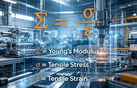
- Young’s Modulus (The Material Property):
Also known as the Elastic Modulus, this is an inherent, unchangeable property of the raw material itself. It measures how much the atomic bonds within the metal or plastic resist stretching. It does not matter if you have a 10-foot thick solid block of Aluminum 6061 or a paper-thin sheet of it; the Young’s Modulus is exactly the same (roughly 10,000,000 psi, or 69 GPa). - Stiffness (The Component Property):
Stiffness is how a specific, physical part resists deflection under a load. Stiffness is a combination of the material’s Young’s Modulus AND the physical geometry (shape) of the part.
The Real-World Reality Check:
You can take a very “soft” material (like standard structural steel) and make an incredibly stiff component out of it by forming it into an I-beam. Conversely, you can take a highly rigid material (like Titanium) and make a very flexible component out of it if you machine it into a thin wire.
As a procurement manager or VP of Engineering, you buy Young’s Modulus by the pound, but you engineer Stiffness in CAD.
How to Calculate Material Stiffness?
When we need to validate a design at EPTAHUB before cutting a rapid aluminum injection mold or setting up a 5-axis CNC mill, we rely on standard linear elastic mechanics.
1. The Basic Component Stiffness Formula (Hooke’s Law)
At its most fundamental level, the stiffness formula for a physical component is derived from Hooke’s Law, which models the part like a spring.

k=F/δ
- $k$ = Stiffness
- $F$ = The applied force (load)
- δ (Delta) = The resulting displacement or deflection
Stiffness Units: In the US, this is measured in lbs/in (pounds per inch of deflection). In the metric system, it is measured in N/m (Newtons per meter).
Business Translation: If a CNC-machined bracket has a stiffness of 5,000 lbs/in, it means it takes 5,000 pounds of force to bend that specific bracket by exactly one inch.
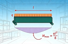
2. The Bending Stiffness Formula (Beams and Chassis)
The basic formula above is great for testing a physical part, but how do you calculate it before the part is manufactured? If you are designing a structural support, you need the stiffness of beam formula (specifically, Bending Stiffness).

Bending Stiffness is the product of the material property (E) and the geometric property (I).
Bending Stiffness = E×I
- $E$ = Young’s Modulus of the material (measured in psi or GPa).
- $I$ = Area Moment of Inertia (a mathematical value based entirely on the cross-sectional shape of the part, usually calculated by your CAD software).
- Bending Stiffness Unit: lb⋅in2 (US) or N⋅m2 (Metric).
This formula is the holy grail of cost-reduction in manufacturing. If a part isn’t stiff enough, rookie engineers will simply swap to a more expensive, higher-modulus material (increasing E). A veteran American engineer will instead change the geometry in CAD (increasing I)—like adding a simple vertical rib to a sheet metal enclosure—which dramatically increases the total stiffness without changing the cheap raw material.
The Eptahub Material Modulus Reference Matrix
To help your team stop guessing, here is a quick-reference matrix of standard manufacturing materials we use daily, ranked by their Young’s Modulus. Notice the massive jump between engineering plastics and industrial metals.
| Material Class | Specific Alloy / Polymer | Young’s Modulus (E) – US (psi) | Young’s Modulus (E) – Metric (GPa) | Typical B2B Application |
|---|---|---|---|---|
| Commodity Plastic | ABS (Injection Molded) | ~ 330,000 psi | ~ 2.3 GPa | Consumer electronics housings. High flex. |
| Engineering Plastic | Polycarbonate (PC) | ~ 380,000 psi | ~ 2.6 GPa | Impact-resistant clear covers, rugged enclosures. |
| Soft Metal | Aluminum 6061-T6 | ~ 10,000,000 psi | ~ 69 GPa | CNC machined baseplates, drone chassis. High strength-to-weight. |
| Hard Metal | 304 Stainless Steel | ~ 28,000,000 psi | ~ 193 GPa | High-stress marine/medical brackets. Very rigid. |
| Tool Steel | A2 or D2 Tool Steel | ~ 30,000,000 psi | ~ 207 GPa | The molds we cut to make your parts. Zero deflection allowed. |
If you design a plastic part with the geometric thickness of a metal part, it will fail because the modulus of plastic is roughly 30 times lower than aluminum. You must design for the material.
The DFM Reality: Geometry is Cheaper Than Metallurgy
As a VP of Engineering or Procurement Manager, you are constantly battling unit costs. Here is a manufacturing secret that we utilize during our DFM (Design for Manufacturing) reviews at EPTAHUB: Steel is cheap. Titanium is expensive. Geometry is free.
When an outsourced CAD file comes across my desk and the part lacks the required stiffness, my first instinct is never to change the raw material. Changing an Aluminum 6061 part to 304 Stainless Steel triples the raw material cost, quadruples the CNC machining time, and ruins your margins.
Instead, we look at the Area Moment of Inertia (I). Because stiffness is heavily dependent on the height of the material relative to the bending load, adding a simple feature—like a small vertical rib, a flange, or a corrugation in sheet metal—can double the stiffness of the component with virtually zero added material or machining cost.
Case Study: The EV Battery Tray Redesign
The Scenario: A mid-sized electric vehicle startup out of Detroit sent us an RFQ for 5,000 custom battery trays. Their engineers designed a flat, 0.25-inch thick solid aluminum plate to hold heavy lithium-ion modules.
The Disaster: When we ran the CAD through our FEA (Finite Element Analysis) software, the flat plate sagged by 0.15 inches under the weight of the batteries. The startup’s internal team panicked and demanded we quote the part out of a much thicker block of heavy Stainless Steel to “make it stiffer.”
The Eptahub Fix: We stopped them before they blew their budget.
- We kept the material as cheap, lightweight Aluminum 6061.
- We reduced the base thickness from 0.25 inches down to 0.125 inches (saving 50% on raw material weight).
- We added a 0.5-inch tall, 90-degree bent flange around the entire perimeter of the tray, and stamped two longitudinal structural ribs down the center.
The Result: By dramatically increasing the Moment of Inertia (I), the new, thinner tray was three times stiffer than the original thick flat plate. We transitioned the part from a slow, expensive CNC milling operation to a high-speed sheet metal stamping operation. The unit cost dropped from 45.00to12.00, and the part actually lost weight. That is the power of understanding the stiffness of beam formula in a commercial setting.
How Do We Measure Stiffness on the Floor?
Theory is great, but how do we prove it before we ship your parts? In the American B2B sector, “trust me” is not an engineering standard. If you are ordering 10,000 units from EPTAHUB, we validate stiffness through a strict two-phase protocol.
Phase 1: Digital Validation (FEA)
Before we cut any metal, we run your .STEP files through FEA (Finite Element Analysis) software like SolidWorks Simulation or Ansys. We digitally apply your specified loads (e.g., 500 lbs of downward force) and the software maps out the exact deflection path using the material’s Young’s Modulus. This catches 90% of geometric failures before they happen.
Phase 2: Physical Validation (Instron Testing)
Once we machine or 3D-print the first physical prototype, we don’t just measure the dimensions with calipers. We place the physical part into a Universal Testing Machine (often referred to generically as an Instron machine). We use hydraulic rams to apply a precise, measured load (F) and use digital dial indicators to measure the exact physical deflection (δ). We then plug those numbers back into Hooke’s Law (k=F/δ) to generate a certified stiffness report for your procurement team.
Engineer’s FAQ: Stiffness in Hardware Procurement
Q1: Our plastic enclosure feels “flimsy.” Should we switch from ABS to Polycarbonate to increase stiffness?
Look at the modulus matrix from Part 1. ABS has a modulus of roughly 330,000 psi. Polycarbonate is around 380,000 psi. That is only a 15% increase in material stiffness, but a massive increase in resin cost and injection molding difficulty. The correct move is to have EPTAHUB redesign your CAD file to add internal “gussets” or ribs to the ABS part. It will be much stiffer and far cheaper.
Q2: We need a part that can survive thousands of repeated bending cycles. Should we use a highly stiff material?
Not necessarily. This is where you cross from “Stiffness” into “Fatigue Life.” Highly stiff materials, like cold-rolled steel, can be brittle. If you forcefully bend them back and forth, they will fatigue and snap. If you need a living hinge or a snap-fit clip, you actually want a material with a lower modulus but high yield strength, like Polypropylene (PP) or Delrin (POM), which can endure high flexural strain without permanent deformation.
Q3: Does heat treating (like T6 tempering on Aluminum) increase the stiffness of the metal?
No. This is a massive, common misconception. Heat treating alters the grain structure of the metal, which drastically increases the Yield Strength (the point at which it permanently bends). However, it does not change the atomic bonds. The Young’s Modulus (and therefore the stiffness) of dead-soft annealed Aluminum and heat-treated T6 Aluminum are exactly the same. They will bend the same amount under a light load, but the T6 will survive a much heavier load before snapping.
Authoritative Engineering References
To ensure your engineering team is operating on rigorous American standards and standard physics, mandate the review of these foundational resources:
- Wikipedia – Young’s Modulus
For a rapid, peer-reviewed overview of the mathematical history and exact formulas governing the elastic modulus of solid mechanics.
Link: Wikipedia – Young’s Modulus